ADAPTEC, INC.
ACB-4000A, ACB-4070
|
| |
|
Data bus: |
None (SCSI to ST506 interface) |
|
Size: |
Drive card |
|
Hard drives supported: |
SCSI to two RLL ST506 drives |
|
Floppy drives supported: |
None |
|
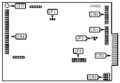
CONNECTIONS | |
|
Function |
Location |
|
20-pin data cable connector-drive 0 |
CN0 |
|
20-pin data cable connector-drive 1 |
CN1 |
|
34-pin control cable connector-hard drive(s) |
CN2 |
|
4-pin connector-DC power |
CN3 |
|
50-pin SCSI connector-to host adapter |
CN4 |
|
SCSI ADDRESS | ||||
|
SCSI ID |
JP5/Jumper 1 |
JP5/Jumper 2 |
JP5/Jumper 3 | |
|
0 |
open |
open |
open | |
|
1 |
closed |
open |
open | |
|
2 |
open |
closed |
open | |
|
3 |
closed |
closed |
open | |
|
4 |
open |
open |
closed | |
|
5 |
closed |
open |
closed | |
|
6 |
open |
closed |
closed | |
| » |
7 |
closed |
closed |
closed |
|
USER CONFIGURABLE SETTINGS | |||
|
Function |
Location |
Setting | |
| » |
Write precomp. disabled (ACB-4000A only) |
JP2 |
pins 1 & 2 closed |
|
Write precomp. same as R.W.C. (ACB-4000A only) |
JP2 |
pins 2 & 3 closed | |
|
Write precomp. to all tracks enabled (ACB-4000A only) |
JP2 |
pins 2 & 4 closed | |
| » |
DMA transfer rate is SYSCLOCK/4 |
JP5/jumper 4 |
closed |
|
DMA transfer rate is DATACLOCK/2 |
JP5/jumper 4 |
open | |
| » |
Extended command set enable - SASI compatible |
JP5/jumper 5 |
closed |
|
Extended command set disabled |
JP5/jumper 5 |
open | |
| » |
Not used |
JP5/jumper 6 |
open |
| » |
Supports the SEEK COMPLETE line during head switches |
JP5/jumper 7 |
closed |
|
SEEK COMPLETE Cmd. not supported |
JP5/jumper 7 |
open | |
| » |
Self-diagnostics enabled |
JP5/jumper 8 |
closed |
|
Normal operation |
JP5/jumper 8 |
open | |
|
MISCELLANEOUS TECHNICAL NOTES |
|
The function of JP1 is to determine the select technique used to interface the host adapter. Soldering Pin 2 to Pin "P" allows for the "pulse" select that is used by controllers designed to work with SASI hosts. Soldering Pin 2 to Pin "H" or "L" allows for the "level" select signal used in accordance with SCSI standards. |