ADAPTEC, INC.
ACB-4525S4000, ACB-4525Z
|
| |
|
Data bus: |
None (SCSI to ESDI interface) |
|
Size: |
Drive card |
|
Hard drives supported: |
SCSI to two RLL ESDI drives |
|
Floppy drives supported: |
None |
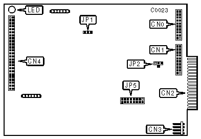
A diagram for these Models was not available, the ACB-4000A is pictured above.
|
CONNECTIONS | |
|
Function |
Location |
|
20-pin data cable connector-drive 0 |
CN0 |
|
20-pin data cable connector-drive 1 |
CN1 |
|
34-pin control cable connector-hard drive(s) |
CN2 |
|
4-pin connector-DC power |
CN3 |
|
50-pin SCSI connector-to host adapter |
CN4 |
|
SCSI ADDRESS | ||||
|
SCSI ID |
JP5/Jumper 1 |
JP5/Jumper 2 |
JP5/Jumper 3 | |
|
0 |
open |
open |
open | |
|
1 |
closed |
open |
open | |
|
2 |
open |
closed |
open | |
|
3 |
closed |
closed |
open | |
|
4 |
open |
open |
closed | |
|
5 |
closed |
open |
closed | |
|
6 |
open |
closed |
closed | |
| » |
7 |
closed |
closed |
closed |
|
USER CONFIGURABLE SETTINGS | |||
|
Function |
Location |
Setting | |
| » |
Not used |
JP2 |
N/A |
| » |
Provides a protocol compatible with ACB-5500 and ACB-4000 families of controllers (4525S4000 only) |
JP5/jumper 4 |
closed |
|
Does not allow for compatibility with ACB-5500 and ACB-4000 controllers (4525S4000 only) |
JP5/jumper 4 |
open | |
| » |
Zero latency default enabled (4525Z only) |
JP5/jumper 4 |
closed |
|
Zero latency default disabled (4525Z only) |
JP5/jumper 4 |
open | |
| » |
Spindle motor starts on command |
JP5/jumper 5 |
closed |
|
Spindle motor starts on power-up |
JP5/jumper 5 |
open | |
| » |
SCSI unit attention disabled |
JP5/jumper 6 |
closed |
|
SCSI unit attention enabled |
JP5/jumper 6 |
open | |
| » |
SCSI parity check enabled |
JP5/jumper 7 |
closed |
|
SCSI parity check disabled |
JP5/jumper 7 |
open | |
| » |
Normal operation |
JP5/jumper 8 |
open |
|
Self-diagnostic enabled |
JP5/jumper 8 |
closed | |
|
MISCELLANEOUS TECHNICAL NOTES |
|
The function of JP1 is to determine the select technique used to interface the host adapter. Soldering Pin-2 to Pin "P" allows for the "pulse" select that is used by controllers designed to work with SCSI hosts. Soldering Pin-2 to Pin "H" or "L" allows for the "handshake" or "level" select signal used in accordance with SCSI standards. Unit attention (JP5/6) is not supported if the JP5/4 jumper is installed on the ACB-4525S4000. |