BCM ADVANCED RESEARCH, INC.
GP-4032
|
Data bus: |
32-bit, VL-bus |
|
Size: |
Three/quarter-length, full-height card |
|
Hard drive supported: |
Two IDE (AT) Interface drives |
|
Floppy drives supported: |
Two 360KB, 720KB, 1.2MB, 1.44MB, or 2.88MB drives |
|
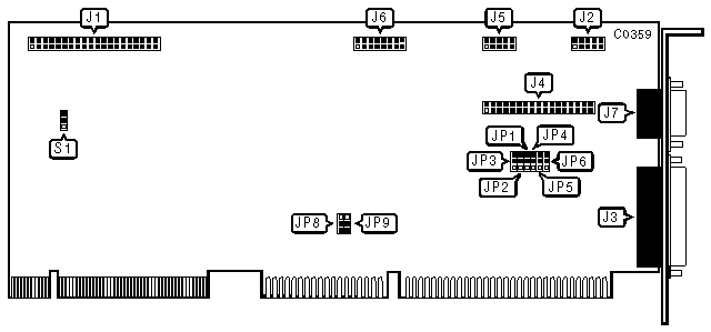
CONNECTIONS | |
|
Function |
Location |
|
40-pin IDE(AT) Interface connector |
J1 |
|
10-pin serial port (COM1/2/3) - internal |
J2 |
|
25-pin parallel port (LPT1/2) - external |
J3 |
|
34-pin control cable connector - floppy drive |
J4 |
|
10-pin serial port (COM2/3/4) - internal |
J5 |
|
15-pin video feature connector - internal |
J6 |
|
15-pin analog VGA port - external |
J7 |
|
PORT CONFIGURATION SETTINGS | ||||||||
|
J4 |
J2 |
J5 |
J3 |
JP1 |
JP2 |
JP3 |
JP4 |
JP5 |
|
Enabled |
COM1 |
COM2 |
LPT1 |
1 & 2 |
1 & 2 |
2 & 3 |
2 & 3 |
1 & 2 |
|
Enabled |
COM1 |
COM2 |
LPT2 |
2 & 3 |
1 & 2 |
2 & 3 |
2 & 3 |
1 & 2 |
|
Enabled |
COM3 |
COM4 |
LPT2 |
1 & 2 |
2 & 3 |
2 & 3 |
2 & 3 |
1 & 2 |
|
Enabled |
COM2 |
COM3 |
LPT1 |
2 & 3 |
2 & 3 |
2 & 3 |
2 & 3 |
1 & 2 |
|
Disabled |
COM1 |
COM2 |
LPT1 |
1 & 2 |
1 & 2 |
2 & 3 |
1 & 2 |
2 & 3 |
|
Disabled |
COM1 |
COM2 |
LPT2 |
2 & 3 |
1 & 2 |
2 & 3 |
1 & 2 |
2 & 3 |
|
Disabled |
COM3 |
COM4 |
LPT2 |
1 & 2 |
2 & 3 |
2 & 3 |
1 & 2 |
2 & 3 |
|
Disabled |
COM2 |
COM3 |
LPT1 |
2 & 3 |
2 & 3 |
2 & 3 |
1 & 2 |
2 & 3 |
|
Enabled |
Disabled |
Disabled |
Disabled |
1 & 2 |
2 & 3 |
2 & 3 |
2 & 3 |
2 & 3 |
|
Disabled |
Disabled |
Disabled |
Disabled |
2 & 3 |
2 & 3 |
2 & 3 |
2 & 3 |
2 & 3 |
|
Note:Pins designated should be in the closed position. | ||||||||
|
USER CONFIGURABLE SETTINGS | |||
|
Function |
Location |
Setting | |
|
» |
Parallel port is uni-directional (printer) |
JP6 |
pins 1 & 2 closed |
|
|
Parallel port is bi-directional (scanner) |
JP6 |
pins 2 & 3 closed |
|
» |
Hard drive enabled |
S1 |
pins 1 & 2 closed |
|
|
Hard drive disabled |
S1 |
pins 2 & 3 closed |
|
VGA WAIT STATE SELECTION | |||
|
Wait state |
JP8 |
JP9 | |
|
|
1 |
pins 2 & 3 closed |
pins 2 & 3 closed |
|
» |
2 |
pins 2 & 3 closed |
pins 1 & 2 closed |
|
|
3 |
pins 1 & 2 closed |
pins 2 & 3 closed |
|
|
4 |
pins 1 & 2 closed |
pins 1 & 2 closed |
|
MISCELLANEOUS TECHNICAL NOTES |
|
The location of jumpers JP7, JP10, JP11, S2, S3, and S4 was not presented by the manufacturer. These jumpers are factory configured to: JP7 - closed, JP10 - pins 1 & 2 closed, JP11 - pins 1 & 2 closed, S2 - pins 2 & 3 closed, S3 - pins 1 & 2 closed, S4 - pins 1 & 2 closed; do not alter. |