RELIALOGIC CORPORATION PRIVATE, LTD.
CA8972F
|
| |
|
Data bus: |
32-bit, VL-Bus |
|
Size: |
Three quarter-length, half-height card |
|
Hard drive supported: |
Two IDE (AT) interface drives |
|
Floppy drives supported: |
360KB, 720KB, 1.2MB, or 1.44MB drives |
|
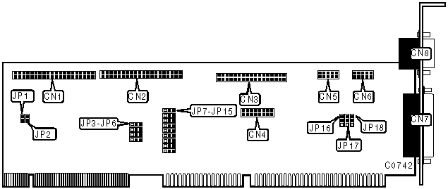
CONNECTIONS | |
|
Function |
Location |
|
40-pin primary IDE(AT) interface |
CN1 |
|
40-pin secondary IDE(AT) interface |
CN2 |
|
34-pin control cable connector - floppy drive |
CN3 |
|
16-pin Game port |
CN4 |
|
10-pin serial port 1 - internal |
CN5 |
|
10-pin serial port 2 - internal |
CN6 |
|
25-pin parallel port |
CN7 |
|
9-pin serial port 1 - external |
CN8 |
|
2-pin drive active LED for primary IDE |
JP1 |
|
2-pin drive active LED for secondary IDE |
JP2 |
|
HDD SPEED CONFIGURATION | ||
|
Speed |
JP3 |
JP4 |
|
0 |
pins 2 & 3 closed |
pins 2 & 3 closed |
|
1 |
pins 1 & 2 closed |
pins 1 & 2 closed |
|
2 |
pins 2 & 3 closed |
pins 1 & 2 closed |
|
3 |
pins 1 & 2 closed |
pins 2 & 3 closed |
|
Note: Speed "0" is the lowest, speed "3" is the highest. | ||
|
USER CONFIGURABLE SETTINGS | |||
|
Function |
Location |
Setting | |
| » |
Primary IDE interface enabled |
JP5 |
pins 1 & 2 closed |
|
Primary IDE interface disabled |
JP5 |
pins 2 & 3 closed | |
| » |
Secondary IDE interface enabled |
JP6 |
pins 1 & 2 closed |
|
Secondary IDE interface disabled |
JP6 |
pins 2 & 3 closed | |
| » |
Floppy drive interface enabled |
JP9 |
pins 1 & 2 closed |
|
Floppy drive interface disabled |
JP9 |
pins 2 & 3 closed | |
| » |
Parallel port is LPT2 |
JP14 |
pins 1 & 2 closed |
|
Parallel port is LPT3 |
JP14 |
pins 2 & 3 closed | |
| » |
Game port enabled |
JP15 |
pins 1 & 2 closed |
|
Game port disabled |
JP15 |
pins 2 & 3 closed | |
| » |
External floppy drive controller enabled |
JP16 |
Pins 1 & 2 closed |
|
External floppy drive controller disabled |
JP16 |
pins 2 & 3 closed | |
|
Note: When enabling the external floppy drive controller, an external floppy drive can be attached to the parallel port. | |||
|
PARALLEL PORT MODE CONFIGURATION | |||
|
MODE |
JP7 |
JP8 | |
| » |
Standard printer |
pins 1 & 2 closed |
pins 2 & 3 closed |
|
ECP |
pins 1 & 2 closed |
pins 1 & 2 closed | |
|
EPP |
pins 2 & 3 closed |
pins 1 & 2 closed | |
|
Disabled |
pins 2 & 3 closed |
pins 2 & 3 closed | |
|
SERIAL PORT 1 CONFIGURATION | |||
|
COM |
JP10 |
JP11 | |
| » |
COM1 |
pins 1 & 2 closed |
pins 1 & 2 closed |
|
COM3 |
pins 2 & 3 closed |
pins 1 & 2 closed | |
|
Disabled |
N/A |
pins 2 & 3 closed | |
|
SERIAL PORT 2 CONFIGURATION | |||
|
COM |
JP12 |
JP13 | |
| » |
COM2 |
pins 1 & 2 closed |
pins 1 & 2 closed |
|
COM4 |
pins 2 & 3 closed |
pins 1 & 2 closed | |
|
Disabled |
N/A |
pins 2 & 3 closed | |
|
DMA SELECTION | |||
|
DMA |
JP17 |
JP18 | |
| » |
DMA1 |
pins 1 & 2 closed |
pins 1 & 2 closed |
|
DMA3 |
pins 2 & 3 closed |
pins 2 & 3 closed | |