UNIDENTIFIED
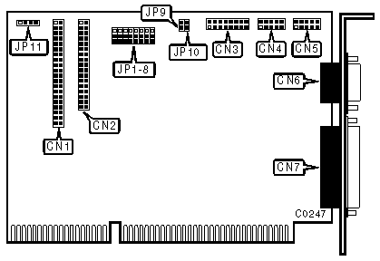
SMART DRIVE I/O ADAPTER
|
|
Data bus: 16-bit, ISA
Size: Half-length, full-height card
Hard drives supported: Two IDE Interface (AT) drives
Floppy drives supported: Two 360KB, 720KB, 1.2MB, or 1.44MB
|
CONNECTIONS | |
|
Function |
Location |
|
40-pin AT Interface (IDE) connector |
CN1 |
|
34-pin control cable connector-floppy drive |
CN2 |
|
15-pin game port |
CN3 |
|
9-pin serial port 2 - internal |
CN4 |
|
9-pin serial port 1 - internal* |
CN5 |
|
9-pin serial port 1 - external* |
CN6 |
|
25-pin parallel port-external |
CN7 |
|
4-pin connector-drive active LED |
CN11 |
|
Note:* These ports share the same I/O port addresses and may not be used at the same time. | |
|
USER CONFIGURABLE SETTINGS | |||
|
Function |
Location |
Setting | |
| » |
Configuration Register set by hardware (jumpers) |
JP1/jumper 1 |
pins 2 & 3 closed |
|
Configuration Register set by software |
JP1/jumper 1 |
pins 1 & 2 closed | |
| » |
Floppy drive enabled |
JP1/jumper 4 |
pins 2 & 3 closed |
|
Floppy drive disabled |
JP1/jumper 4 |
pins 1 & 2 closed | |
| » |
Factory configured - do not alter |
JP1/jumper 5 |
pins 1 & 2 closed |
| » |
Two Floppy drives supported |
JP1/jumper 5 |
pins 2 & 3 closed |
| » |
Hard drive enabled |
JP9 and JP10 |
closed |
|
Hard drive disabled |
JP9 and JP10 |
open | |
|
SERIAL PORT CONFIGURATION | ||||
|
CN4 |
CN5/6 |
JP1/jumper 6 |
JP1/jumper 7 |
JP1/jumper 8 |
|
COM2 |
COM1 |
pins 2 & 3 |
pins 2 & 3 |
pins 2 & 3 |
|
Disabled |
COM1 |
pins 2 & 3 |
pins 2 & 3 |
pins 1 & 2 |
|
COM1 |
COM2 |
pins 2 & 3 |
pins 1 & 2 |
pins 2 & 3 |
|
COM1 |
Disabled |
pins 1 & 2 |
pins 1 & 2 |
pins 2 & 3 |
|
COM2 |
Disabled |
pins 1 & 2 |
pins 2 & 3 |
pins 2 & 3 |
|
Disabled |
COM2 |
pins 2 & 3 |
pins 1 & 2 |
pins 1 & 2 |
|
Disabled |
Disabled |
pins 1 & 2 |
N/A |
pins 1 & 2 |
|
Note:Pins designated should be in the closed position. | ||||
|
PARALLEL PORT (CN7) CONFIGURATION | |||
|
LPT |
JP1/jumper 2 |
JP1/jumper 3 | |
| » |
LPT2 (378-37Ah) |
pins 2 & 3 closed |
pins 2 & 3 closed |
|
LPT3 (278-27Ah) |
pins 1 & 2 closed |
pins 2 & 3 closed | |
|
LPT1 (3BC-3BEh) |
pins 2 & 3 closed |
pins 1 & 2 closed | |
|
Disabled |
pins 1 & 2 closed |
pins 1 & 2 closed | |