UNIDENTIFIED
SIO-7, SIO-8, SIO-11
|
|
Data bus: 16-bit, ISA
Size: Half-length, full-height card
Hard drives supported: Two IDE (AT) Interface drives
Floppy drives supported: Two 360KB, 720KB, 1.2MB or 1.44MB drives
|
CONNECTIONS | |
|
Function |
Location |
|
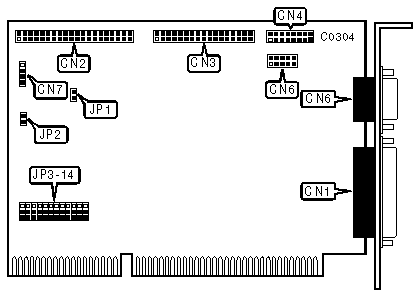
25-pin parallel port (LPT1/2)-external |
CN1 |
|
40-pin IDE (AT) Interface connector-internal |
CN2 |
|
34-pin control cable connector floppy drive |
CN3 |
|
16-pin game port-internal (SIO-7 and SIO-11 only) |
CN4 |
|
9-pin serial port 2 (COM2/4)-internal |
CN5 |
|
9-pin serial port 1 (COM1/3)-external |
CN6 |
|
4-pin connector-drive active LED |
CN7 |
|
USER CONFIGURABLE SETTINGS | |||
|
Function |
Location |
Setting | |
| » |
I/O Channel Ready enabled |
JP1 |
closed |
|
I/O Channel Ready disabled |
JP1 |
open | |
| » |
Game Port (CN4) enabled |
JP2 |
closed |
|
Game Port (CN4) disabled |
JP2 |
open | |
| » |
Serial Port 2 (CN5) uses IRQ3 |
JP3 |
pins 1 & 2 closed |
|
Serial Port 1 (CN6) uses IRQ3 |
JP3 |
pins 2 & 3 closed | |
|
IRQ3 disabled |
JP3 |
open | |
| » |
IRQ9 disabled |
JP4 |
open |
|
Serial Port 2 (CN5) uses IRQ9 |
JP4 |
pins 1 & 2 closed | |
|
Serial Port 1 (CN6) uses IRQ9 |
JP4 |
pins 2 & 3 closed | |
|
Serial Port 2 (CN5) uses IRQ4 |
JP5 |
pins 1 & 2 closed | |
| » |
Serial Port 1 (CN6) uses IRQ4 |
JP5 |
pins 2 & 3 closed |
|
IRQ4 disabled |
JP5 |
open | |
| » |
IRQ5 disabled |
JP6 |
open |
|
Serial Port 2 (CN5) uses IRQ5 |
JP6 |
pins 1 & 2 closed | |
|
Serial Port 1 (CN6) uses IRQ5 |
JP6 |
pins 2 & 3 closed | |
| » |
Parallel Port (CN1) uses IRQ7 |
JP7 |
pins 1 & 2 closed |
|
Parallel Port (CN1) uses IRQ5 |
JP7 |
pins 2 & 3 closed | |
|
Parallel Port IRQ disabled |
JP7 |
open | |
| » |
Floppy drive controller enabled |
JP8 |
pins 2 & 3 closed |
|
Floppy drive controller disabled |
JP8 |
pins 1 & 2 closed | |
| » |
Hard drive controller enabled |
JP14 |
pins 2 & 3 closed |
|
Hard drive controller disabled |
JP14 |
pins 1 & 2 closed | |
|
PARALLEL PORT (CN1) CONFIGURATION | |||
|
LPT |
JP9 |
JP10 | |
| » |
LPT2 |
pins 1 & 2 closed |
pins 2 & 3 closed |
|
LPT1 |
pins 2 & 3 closed |
pins 1 & 2 closed | |
|
LPT3 |
pins 2 & 3 closed |
pins 2 & 3 closed | |
|
Disabled |
pins 1 & 2 closed |
pins 1 & 2 closed | |
|
SERIAL PORT CONFIGURATION | |||||
|
Serial Port 1(CN6) |
Serial Port 2 (CN5) |
JP11 |
JP12 |
JP13 | |
| » |
COM1 |
COM2 |
pins 2 & 3 |
pins 2 & 3 |
pins 1 & 2 |
|
COM2 |
COM1 |
pins 2 & 3 |
pins 2 & 3 |
pins 2 & 3 | |
|
COM2 |
Disabled |
pins 2 & 3 |
pins 1 & 2 |
pins 2 & 3 | |
|
COM1 |
Disabled |
pins 2 & 3 |
pins 1 & 2 |
pins 1 & 2 | |
|
Disabled |
COM1 |
pins 1 & 2 |
pins 2 & 3 |
pins 2 & 3 | |
|
Disabled |
COM2 |
pins 1 & 2 |
pins 2 & 3 |
pins 1 & 2 | |
|
COM3 |
COM4 |
pins 1 & 2 |
pins 1 & 2 |
pins 2 & 3 | |
|
Disabled |
Disabled |
pins 1 & 2 |
pins 1 & 2 |
pins 1 & 2 | |
|
Note:Pins designated should be in the closed position. | |||||