ATLANTIC COMPUTER PRODUCTS, INC.
GP4530
|
| |
|
Data bus: |
32-bit, VL-bus |
|
Size: |
Three/quarter-length, full-height card |
|
Hard drive supported: |
Two IDE (AT) interface drives |
|
Floppy drives supported: |
Two 360KB, 720KB, 1.2MB, 1.44MB, or 2.88MB drives |
|
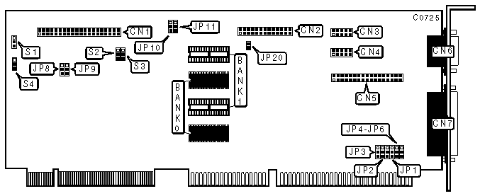
CONNECTIONS | |
|
Function |
Location |
|
40-pin IDE (AT) Interface connector |
CN1 |
|
VGA feature connector |
CN2 |
|
10-pin serial port 2 |
CN3 |
|
10-pin serial port 1 |
CN4 |
|
34-pin control cable connector - floppy drive |
CN5 |
|
15-pin analog video connector |
CN6 |
|
25-pin parallel port |
CN7 |
|
"Green Feature" connector |
JP20 |
|
USER CONFIGURABLE SETTINGS | |||
|
Function |
Location |
Setting | |
| » |
Factory configured - do not alter |
JP3 |
pins 2 & 3 closed |
| » |
Parallel port used for printer |
JP6 |
pins 1 & 2 closed |
|
Parallel port used for scanner |
JP6 |
pins 2 & 3 closed | |
| » |
IDE port enabled |
S1 |
pins 1 & 2 closed |
|
IDE port disabled |
S1 |
pins 2 & 3 closed | |
| » |
Factory configured - do not alter |
S2 |
pins 2 & 3 closed |
| » |
Factory configured - do not alter |
S3 |
pins 1 & 2 closed |
| » |
Factory configured - do not alter |
S4 |
pins 1 & 2 closed |
|
I/O PORTS CONFIGURATION | ||||||||
|
Floppy |
Serial 1 |
Serial 2 |
Parallel |
JP1 |
JP2 |
JP4 |
JP5 | |
| » |
Enabled |
COM1 |
COM2 |
LPT1 |
1 & 2 |
1 & 2 |
2 & 3 |
1 & 2 |
|
Enabled |
COM1 |
COM2 |
LPT2 |
2 & 3 |
1 & 2 |
2 & 3 |
1 & 2 | |
|
Enabled |
COM3 |
COM4 |
LPT2 |
1 & 2 |
2 & 3 |
2 & 3 |
1 & 2 | |
|
Enabled |
COM2 |
COM3 |
LPT1 |
2 & 3 |
2 & 3 |
2 & 3 |
1 & 2 | |
|
Disabled |
COM1 |
COM2 |
LPT1 |
1 & 2 |
1 & 2 |
1 & 2 |
2 & 3 | |
|
Disabled |
COM1 |
COM2 |
LPT2 |
2 & 3 |
1 & 2 |
1 & 2 |
2 & 3 | |
|
Disabled |
COM3 |
COM4 |
LPT2 |
1 & 2 |
2 & 3 |
1 & 2 |
2 & 3 | |
|
Disabled |
COM2 |
COM3 |
LPT1 |
2 & 3 |
2 & 3 |
1 & 2 |
2 & 3 | |
|
Enabled |
Disabled |
Disabled |
Disabled |
1 & 2 |
2 & 3 |
2 & 3 |
2 & 3 | |
|
Disabled |
Disabled |
Disabled |
Disabled |
2 & 3 |
2 & 3 |
2 & 3 |
2 & 3 | |
|
Note:The pins indicated are in the closed position. | ||||||||
|
WAIT STATE | |||
|
Setting |
JP8 |
JP9 | |
| » |
Wait State 2 enabled |
pins 2 & 3 closed |
pins 2 & 3 closed |
|
Wait State 1 enabled |
pins 2 & 3 closed |
pins 1 & 2 closed | |
|
Wait State 3 enabled |
pins 1 & 2 closed |
pins 2 & 3 closed | |
|
Wait State 4 enabled |
pins 1 & 2 closed |
pins 1 & 2 closed | |
|
VIDEO MEMORY CONFIGURATION | |||||
|
Memory Size |
JP10 |
JP11 |
Bank 0 |
Bank 1 | |
| » |
1MB |
pins 2 & 3 closed |
pins 1 & 2 closed |
(2) 512K x 8 |
None |
|
2MB |
pins 2 & 3 closed |
pins 2 & 3 closed |
(2) 512K x 8 |
(2) 512K x 8 | |