AMPRO COMPUTERS, INC.
LITTLE BOARD/486
|
Processor |
80486SX/80487SX/80486DX |
|
Processor Speed |
20/33MHz |
|
Chip Set |
Ampro |
|
Max. onboard DRAM |
16MB |
|
Cache |
32KB optional (location unknown) |
|
BIOS |
Award |
|
Dimensions |
330mm x 218mm |
|
I/O Options |
Floppy drive interface, IDE interface, parallel port, SCSI connector, serial ports (2) |
|
NPU Options |
None |
|
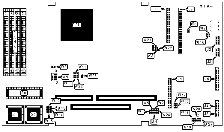
CONNECTIONS | |||
|
Purpose |
Location |
Purpose |
Location |
|
Power connector |
J1 |
Parallel port |
J6 |
|
Serial port (COM2) |
J2 |
SCSI interface |
J7 |
|
Serial port (COM1) |
J3 |
Floppy drive interface |
J8 |
|
Utility connector |
J4 |
IDE interface |
J11 |
|
Keyboard |
J5 |
Power J1-1 to +12V BUS |
W7 |
|
USER CONFIGURABLE SETTINGS | |||
|
Function |
Jumper/Switch |
Position | |
| » |
SCSI controller enabled |
W1 |
Closed |
|
SCSI controller disabled |
W1 |
Open | |
| » |
Factory configured - do not alter |
W3 |
N/A |
| » |
SCSI controller select IRQ15 |
W5 |
Open |
|
SCSI controller select IRQ11 |
W5 |
Closed | |
| » |
SCSI termination power enabled |
W6 |
Open |
|
SCSI termination power disabled |
W6 |
Closed | |
| » |
Factory configured - do not alter |
W10 |
Closed |
| » |
Factory configured - do not alter |
W11 |
pins 1 & 2 closed |
| » |
Flash EPROM programming power enabled |
W16 |
Open |
|
Flash EPROm programming power disabled |
W16 |
Closed | |
| » |
Watchdog timer select I/O CHCK |
W17 |
pins 1 & 2 closed |
|
Watchdog timer select reset |
W17 |
pins 2 & 3 closed | |
|
Watchdog timer disabled |
W17 |
Open | |
| » |
Floppy drive interface enabled |
W18 |
Open |
|
Floppy drive interface disabled |
W18 |
Closed | |
| » |
Floppy precompensation (PCVAL) selection |
W19 |
Open |
|
Floppy precompensation (PCVAL) none |
W19 |
Closed | |
| » |
Floppy drive select IRQ6 |
W20 & W27 |
Closed |
|
Floppy drive select IRQ6 disabled |
W20 & W27 |
Open | |
| » |
External cache enabled |
W21 |
Open |
|
External cache disabled |
W21 |
Closed | |
| » |
Factory configured - do not alter |
W22 |
N/A |
| » |
Power fail NMI enabled |
W23 |
Open |
|
Power fail NMI disabled |
W23 |
Closed | |
| » |
Parallel port interrrupt option select via setup |
W24 |
Open |
|
Parallel port interrrupt option disabled |
W24 |
Closed | |
|
Note: W18 may either be an option or is not user configurable. | |||
|
DRAM CONFIGURATION | |
|
Size |
Bank 0 |
|
1MB |
(4) 256K x 9 |
|
4MB |
(4) 1M x 9 |
|
16MB |
(4) 4M x 9 |
|
CACHE CONFIGURATION | |||||
|
Cache |
DRAM |
U9 |
U10 |
Tag U12 |
Tag U13 |
|
32KB |
4MB |
(2) 8K x 8 |
(2) 8K x 8 |
(2) 8K x 8 |
NONE |
|
32KB |
16MB |
(2) 8K x 8 |
(2) 8K x 8 |
(2) 8K x 8 |
(2) 8K x 8 |
|
EPROM CONFIGURATION (S0) | |||
|
EPROM |
W8 |
W9 |
W25 |
|
27C256 |
Open |
pins 7 & 8, 10 & 11 |
pins 1 & 2 |
|
27C512 |
Open |
pins 1 & 4, 7 & 8, 10 & 11 |
pins 1 & 2 |
|
27C010 |
Open |
pins 1 & 4, 2 & 5, 6 & 9, 7 & 8 |
pins 1 & 2 |
|
27C020 |
Open |
pins 1 & 4, 2 & 5, 6 & 9, 7 & 8, 11 & 12 |
pins 1 & 2 |
|
27C040 |
Open |
pins 1 & 4, 2 & 3, 6 & 9, 7 & 8, 11 & 12 |
pins 1 & 2 |
|
27C080 |
Closed |
pins 1 & 4, 2 & 3, 7 & 8, 11 & 12 |
pins 1 & 2 |
|
62256 |
Open |
pins 4 & 7, 5 & 8, 10 & 11 |
pins 1 & 2 or 2 & 3 |
|
628128 |
Open |
pins 1 & 2, 4 & 7, 5 & 8, 10 & 11 |
pins 1 & 2 or 2 & 3 |
|
uPD434000 |
Open |
pins 1 & 2, 3 & 6, 4 & 7, 5 & 8, 11 & 12 |
pins 1 & 2 or 2 & 3 |
|
28F256 |
Open |
pins 2 & 5, 6 & 9, 7 & 8 |
pins 1 & 2 |
|
28F512 |
Open |
pins 1 & 4, 2 & 5, 6 & 9, 7 & 8 |
pins 1 & 2 |
|
28F010 |
Open |
pins 1 & 4, 2 & 5, 6 & 9, 7 & 8 |
pins 1 & 2 |
|
28F020 |
Open |
pins 1 & 4, 2 & 5, 6 & 9, 7 & 8, 11 & 12 |
pins 1 & 2 |
|
Note:Pins designated should be in the closed position. | |||
|
EPROM/FLASH EPROM CONFIGURATION (S1 & S2) | ||||
|
EPROM |
W12 |
W13 |
W14 |
W15 |
|
128KB |
pins 2 & 3 closed |
pins 2 & 3 closed |
pins 2 & 3 closed |
pins 2 & 3 closed |
|
256KB |
pins 2 & 3 closed |
pins 2 & 3 closed |
pins 2 & 3 closed |
pins 2 & 3 closed |
|
SCSI CONTROLLER CONFIGURATION | ||
|
DMA |
W2 |
W4 |
|
6 |
pins 1 & 2 closed |
Open |
|
0 |
pins 2 & 3 closed |
Closed |
|
UTILITY CONNECTOR (J4) PIN CONFIGURATION | ||
|
Pin |
Signal Name |
Function |
|
1 |
Speaker |
Audio signal |
|
2 |
Speaker |
Ground |
|
3 |
Ground |
To one side of Reset button |
|
4 |
Reset |
To other side of Reset button |
|
5 |
LED Cathode |
Ground return |
|
6 |
LED anode |
Current source (+5v through 330 ohms) |
|
7 |
Ground |
Ground return |
|
8 |
+12V power |
Connected to P1 pin B9 |
|
9 |
-5V power |
Connected to P1 pin B5 |
|
10 |
-12V power |
Connected to P1 pin B7 |
|
11 |
Ground |
Ground return |
|
12 |
POWERGOOD |
Power supply status |
|
WATCHDOG TIMER CONFIGURATION | ||
|
Setting |
W17 |
W23 |
|
Disabled |
Open |
Open |
|
IOCHCK (NMI) |
Pins 1 & 2 closed |
Open |
|
Reset |
pins 2 & 3 closed |
N/A |
|
Note:I/O channel check is the bus signal that triggers a non-maskable interrupt (NMI) Reset is a hard reset signal, the same as pressing the reset button. | ||