HYUNDAI ELECTRONICS, INC.
SUPER 386C
|
Processor |
80386DX |
|
Processor Speed |
20MHz |
|
Chip Set |
VLSI |
|
Max. Onboard DRAM |
8MB (on CPU/NPU/MEM card) |
|
Cache |
None |
|
BIOS |
Phoenix |
|
Dimensions |
350mm x 304mm |
|
I/O Options |
Serial port, parallel port, floppy drive interface, IDE interface, proprietary cpu/npu/memory card, proprietary external memory card slot (on CPU card) |
|
NPU Options |
80387 (on CPU/NPU/MEM card) |
|
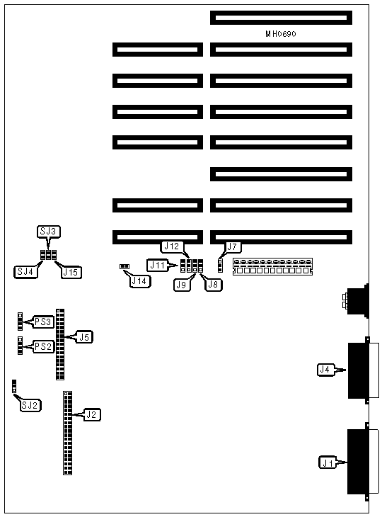
CONNECTIONS | |||
|
Purpose |
Location |
Purpose |
Location |
|
Parallel port |
J1 |
Floppy drive interface |
J5 |
|
IDE interface |
J2 |
Keyboard & power good signal |
J7 |
|
Serial port |
J4 |
Auxiliary CPU card power |
PS2 & PS3 |
|
Notes:J7 is connected to J1 on the CPU card. PS2 & PS3 are connected to PS1 & PS2 on the CPU card when an NPU is installed. | |||
|
USER CONFIGURABLE SETTINGS | |||
|
Function |
Jumper |
Position | |
| » |
Serial port select COM1 |
J8 & J9 |
pins 1 & 2 closed |
|
Serial port select COM2 |
J8 & J9 |
pins 2 & 3 closed | |
|
Serial port disabled |
J8 & J9 |
Open | |
| » |
Parallel port select LPT1 |
J11 & J12 |
pins 1 & 2 closed |
|
Parallel port select LPT2 |
J11 & J12 |
pins 2 & 3 closed | |
|
Parallel port disabled |
J11 & J12 |
Open | |
| » |
Floppy drive interface enabled |
J14 |
Closed |
|
Floppy drive interface enabled |
J14 |
Open | |
| » |
IDE interface enabled |
J15 |
Closed |
|
IDE interface disabled |
J15 |
Open | |
| » |
Factory configured - do not alter |
SJ2 |
pins 2 & 3 closed |
| » |
Factory configured - do not alter |
SJ3 |
N/A |
| » |
Factory configured - do not alter |
SJ4 |
N/A |
|
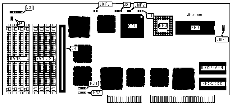
DRAM CONFIGURATION | ||
|
Size |
Bank 0 |
Bank 1 |
|
1MB |
(4) 256K x 9 |
NONE |
|
2MB |
(4) 256K x 9 |
(4) 256K x 9 |
|
4MB |
(4) 1M x 9 |
NONE |
|
8MB |
(4) 1M x 9 |
(4) 1M x 9 |
|
CONNECTIONS | |||
|
Purpose |
Location |
Purpose |
Location |
|
Keyboard & power good signal |
J1 |
Reset switch |
J3 pins 6 & 7 |
|
External battery |
J2 |
Proprietary external memory card |
J4 |
|
Turbo LED |
J3 pins 1 - 3 |
Speaker |
J5 |
|
Keylock |
J3 pins 4 & 5 |
Auxiliary power |
PS1 & PS2 |
|
Notes:J1 connects to J7 on the main board. PS1 & PS2 connect to PS2 & PS3 on the main board when an NPU is installed. | |||
|
USER CONFIGURABLE SETTINGS | |||
|
Function |
Jumper |
Position | |
| » |
Monitor type select color |
JMP1 |
pins 2 & 3 closed |
|
Monitor type select monochrome |
JMP1 |
pins 1 & 2 closed | |
| » |
Page-mode enabled |
JMP2 |
Closed |
|
Page-mode disabled |
JMP2 |
Open | |
| » |
NPU enabled |
JMP3 |
Closed |
|
NPU disabled |
JMP3 |
Open | |
|
Note:When enabling the NPU, PS1 & PS2 on the CPU card should be connected to PS2 & PS3 on the main board. | |||