INTERLOGIC INDUSTRIES
SC386DX
|
Processor |
80386DX |
|
Processor Speed |
33MHz |
|
Chip Set |
OPTI |
|
Max. Onboard DRAM |
32MB |
|
SRAM Cache |
32/64/128/256KB |
|
BIOS |
Award |
|
Dimensions |
350mm x 125mm |
|
I/O Options |
Floppy drive interface, IDE interface parallel port, serial port (2), PS/2 keyboard port |
|
NPU Options |
80387DX |
|
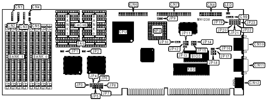
CONNECTIONS | |||
|
Purpose |
Location |
Purpose |
Location |
|
Auxiliary keyboard |
CN1 |
Parallel port |
CN8 |
|
Keylock |
CN2 |
External battery |
CN9 |
|
Speaker |
CN3 |
Serial port 1 |
CN10 |
|
Reset switch |
CN4 |
Serial port 2 |
CN11 |
|
IDE interface LED |
CN5 |
PS/2 keyboard |
CN12 |
|
Floppy drive interface |
CN6 |
Power LED |
LED |
|
IDE interface |
CN7 |
Turbo switch |
JP3 |
|
USER CONFIGURABLE SETTINGS | |||
|
Function |
Jumper |
Position | |
| » |
Factory configured - do not alter |
JP1 |
closed |
| » |
IDE interface (CN7) enabled |
JP9 |
pins 1 & 2 closed |
|
IDE interface (CN7) disabled |
JP9 |
pins2 & 3 closed | |
| » |
Parallel port (CN8) select LPT2 (I/O address 378-37Fh) |
JP12 |
pins 1 & 2 closed |
|
Parallel port (CN8) select LPT3 (I/O address 278-27Fh) |
JP12 |
pins 2 & 3 closed | |
| » |
Monitor type select color |
JP13 |
closed |
|
Monitor type select monochrome |
JP13 |
open | |
| » |
Floppy drive interface (CN6) enabled |
JP14 |
pins 1 & 2 closed |
|
Floppy drive interface (CN6) disabled |
JP14 |
pins 2 & 3 closed | |
| » |
Parallel port (CN8) interrupt select IRQ7 (LPT2) |
JP15 |
pins 1 & 2 closed |
|
Parallel port (CN8) interrupt select IRQ5 (LPT3) |
JP15 |
pins 2 & 3 closed | |
| » |
Watchdog Timer interval select 500ms |
JP16 |
closed |
|
Watchdog Timer interval select 1 second |
JP16 |
open | |
| » |
Watchdog Timer mode select system reset after time-out |
JP17 |
pins 1 & 2 closed |
|
Watchdog Timer mode select low IOCHK# NMI after time-out |
JP17 |
pins 2 & 3 closed | |
|
Watchdog Timer mode select disabled |
JP17 |
open | |
| » |
CMOS memory normal operation |
JP18 |
pins 1 & 2 closed |
|
CMOS memory clear |
JP18 |
pins 2 & 3 closed | |
| » |
Parallel port (CN8) enabled |
JP21 |
pins 1 & 2 closed |
|
Parallel port (CN8) disabled |
JP21 |
pins 2 & 3 closed | |
|
SERIAL PORT CONFIGURATION | |||
|
Function |
Jumper |
Position | |
| » |
Serial port 1 (CN10) enabled |
JP23 |
pins 1 & 2 closed |
|
Serial port 1 (CN10) disabled |
JP23 |
pins 2 & 3 closed | |
| » |
Serial port 1 (CN10) select COM1 (I/O address 3F8-3FFh) |
JP22 |
pins 1 & 2 closed |
|
Serial port 1 (CN10) select COM3 (I/O address 3E8-3EFh) |
JP22 |
pins 2 & 3 closed | |
| » |
Serial port 1 (CN10) interrupt select IRQ4 |
JP11 |
pins 1 & 2 closed |
|
Serial port 1 (CN10) interrupt select IRQ3 |
JP11 |
pins 2 & 3 closed | |
| » |
Serial port 2 (CN11) enabled |
JP20 |
pins 1 & 2 closed |
|
Serial port 2 (CN11) disabled |
JP20 |
pins 2 & 3 closed | |
| » |
Serial port 2 (CN11) select COM2 (I/O address 2F8-2FFh) |
JP19 |
pins 1 & 2 closed |
|
Serial port 2 (CN11) select COM4 (I/O address 2E8-2EFh) |
JP19 |
pins 2 & 3 closed | |
| » |
Serial port 2 (CN11) interrupt select IRQ3 |
JP10 |
pins 1 & 2 closed |
|
Serial port 2 (CN11) interrupt select IRQ4 |
JP10 |
pins 2 & 3 closed | |
|
DRAM CONFIGURATION | ||
|
Size |
Bank 0 |
Bank 1 |
|
1MB |
(4) 256K x 9 |
NONE |
|
2MB |
(4) 256K x 9 |
(4) 256K x 9 |
|
4MB |
(4) 1M x 9 |
NONE |
|
5MB |
(4) 256K x 9 |
(4) 1M x 9 |
|
8MB |
(4) 1M x 9 |
(4) 1M x 9 |
|
16MB |
(4) 4M x 9 |
NONE |
|
20MB |
(4) 4M x 9 |
(4) 1M x 9 |
|
20MB |
(4) 1M x 9 |
(4) 4M x 9 |
|
32MB |
(4) 4M x 9 |
(4) 4M x 9 |
|
SRAM CONFIGURATION | ||||
|
Size |
Cacheable Memory |
Cache SRAM |
Location |
TAG |
|
32KB |
8MB maximum |
(4) 8K x 8 |
Bank 0 |
(1) 8K x 8 |
|
64KB |
16MB maximum |
(8) 8K x 8 |
Banks 0 & 1 |
(2) 8K x 8 |
|
128KB |
32MB maximum |
(4) 32K x 8 |
Bank 0 |
(1) 32K x 8 |
|
256KB |
64MB maximum |
(8) 32K x 8 |
Banks 0 & 1 |
(2) 32K x 8 |
|
SRAM JUMPER CONFIGURATION | ||||||
|
Size |
JP2 |
JP4 |
JP5 |
JP6 |
JP7 |
JP8 |
|
32KB |
open |
pins 1 & 2 |
open |
pins 1 & 2 |
open |
pins 2 & 3 |
|
64KB |
open |
pins 1 & 2 |
pins 1 & 2 |
pins 2 & 3 |
pins 2 & 3 |
pins 1 & 2 |
|
128KB |
pins 1 & 2 |
pins 2 & 3 |
pins 1 & 2 |
pins 2 & 3 |
pins 2 & 3 |
pins 1 & 2 |
|
256KB |
pins 1 & 2 |
pins 2 & 3 |
pins 2 & 3 |
pins 2 & 3 |
pins 1 & 2 |
pins 1 & 2 |
|
Note:Pins designated should be in the closed position. | ||||||