ICL
MX486
|
Processor |
80486DX |
|
Processor Speed |
33/50MHz |
|
Chip Set |
Unidentified |
|
Max. Onboard DRAM |
64MB |
|
Cache |
Unidentified |
|
BIOS |
Unidentified |
|
Dimensions |
355mm x 305mm |
|
I/O Options |
LCD/BIOS slot, local bus slots, external memory card, external processor board, serial ports (2), parallel port, PS/2 mouse interface, floppy drive interface, IDE interface, LCD interface |
|
NPU Options |
4167 |
|
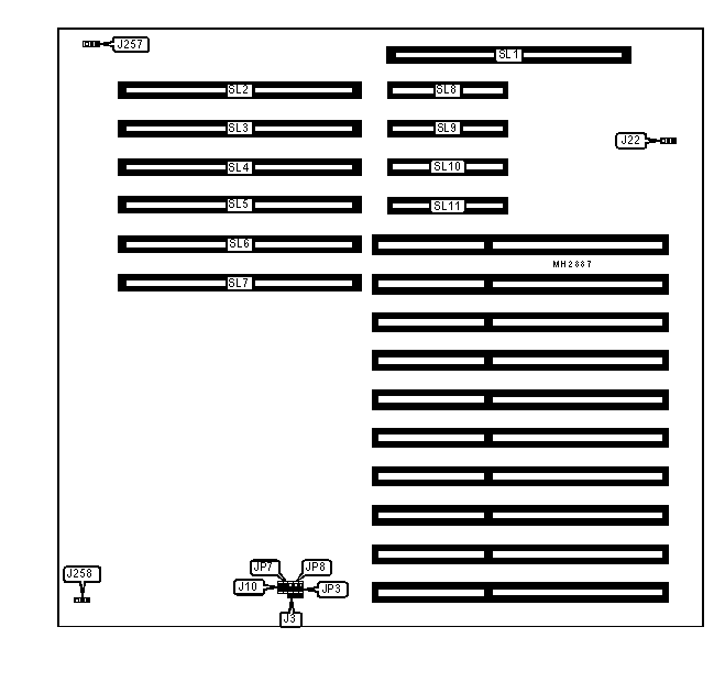
CONNECTIONS | |||
|
Purpose |
Location |
Purpose |
Location |
|
LCD/BIOS slot |
SL1 |
Local bus slots extension slots |
SL8 - SL11 |
|
Local bus slots |
SL2 - SL7 | ||
|
USER CONFIGURABLE SETTINGS | |||
|
Function |
Jumper |
Position | |
|
» |
Multiprocessing type select asymmetric |
J3 |
pins 2 & 3 closed |
|
Multiprocessing type select symmetric |
J3 |
pins 1 & 2 closed | |
|
» |
CPU speed select 33MHz used |
J10 |
Open |
|
CPU speed select 33MHz not used |
J10 |
Closed | |
|
» |
Temperature sensor for second 486/33 board in slot 13 |
J22 |
Open |
|
Temperature sensor for second 486/50 board in slot 14 |
J22 |
Closed | |
|
» |
Factory configured - do not alter |
J257 |
N/A |
|
» |
Factory configured - do not alter |
J258 |
N/A |
|
» |
ISP INT to CPU1 unlatched |
JP3 |
pins 1 & 2 closed |
|
ISP INT to CPU1 latched |
JP3 |
pins 2 & 3 closed | |
|
» |
I/O cycles long wait enabled |
JP7 |
Closed |
|
I/O cycles long wait disabled |
JP7 |
Open | |
|
» |
Cache type select programmed by software |
JP8 |
pins 1 & 2 closed |
|
Cache type select write back |
JP8 |
pins 2 & 3 closed | |
|
Cache type select write through |
JP8 |
Open | |
|
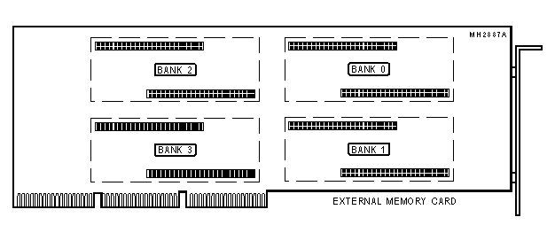
DRAM CONFIGURATION | ||||
|
Size |
Bank 0 |
Bank 1 |
Bank 2 |
Bank 3 |
|
8MB |
8MB |
NONE |
NONE |
NONE |
|
12MB |
8MB |
4MB |
NONE |
NONE |
|
16MB |
8MB |
4MB |
4MB |
NONE |
|
16MB |
8MB |
8MB |
NONE |
NONE |
|
16MB |
16MB |
NONE |
NONE |
NONE |
|
24MB |
8MB |
4MB |
4MB |
8MB |
|
24MB |
8MB |
8MB |
8MB |
NONE |
|
24MB |
8MB |
16MB |
NONE |
NONE |
|
32MB |
8MB |
8MB |
8MB |
8MB |
|
32MB |
16MB |
16MB |
NONE |
NONE |
|
40MB |
8MB |
16MB |
16MB |
NONE |
|
48MB |
16MB |
16MB |
16MB |
NONE |
|
56MB |
8MB |
16MB |
16MB |
16MB |
|
64MB |
16MB |
16MB |
16MB |
16MB |
|
Note: Memory is installed by using ICL modules. | ||||
|
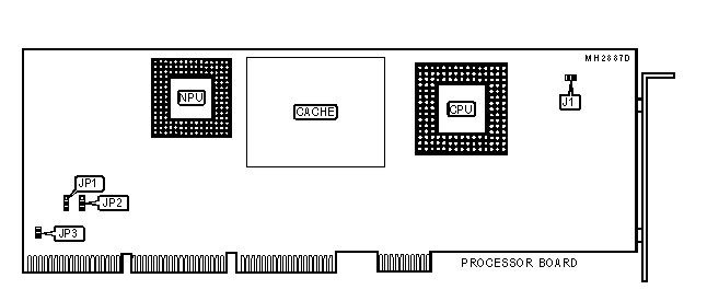
USER CONFIGURABLE SETTINGS | |||
|
Function |
Jumper |
Position | |
|
» |
Factory configured - do not alter |
J1 |
N/A |
|
» |
Factory configured - do not alter |
JP1 |
pins 2 & 3 closed |
|
» |
Factory configured - do not alter |
JP2 |
pins 1 & 2 closed |
|
» |
Factory configured - do not alter |
JP3 |
Closed |
|
CACHE CONFIGURATION |
|
Note: The size and configuration of the cache is unidentified. |
|
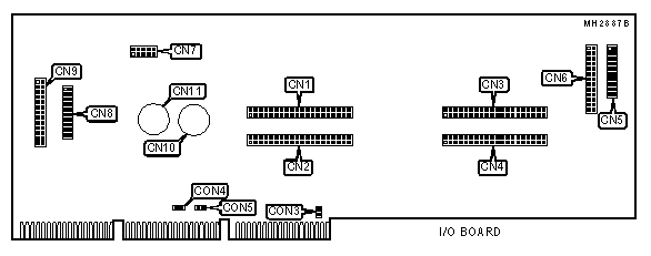
CONNECTIONS | |||
|
Purpose |
Location |
Purpose |
Location |
|
System board connector |
CN1 |
Serial port 1 |
CN7 |
|
System board connector |
CN2 |
Serial port 2 |
CN8 |
|
System board connector |
CN3 |
Parallel port |
CN9 |
|
System board connector |
CN4 |
PS/2 mouse connector |
CN10 |
|
Chassis fan power |
CN5 |
Keyboard connector |
CN11 |
|
Chassis fan power |
CN6 | ||
|
Note: Jumper sizes may not be exact. They are shown for location purposes only. | |||
|
USER CONFIGURABLE SETTINGS | |||
|
Function |
Jumper |
Position | |
|
» |
IRQ select IRQ7 |
CON3 |
pins 2 & 3 closed |
|
IRQ select IRQ5 |
CON3 |
pins 1 & 2 closed | |
|
» |
Motor drive spindle speed select single speed |
CON4 |
Open |
|
Motor drive spindle speed select double speed |
CON4 |
Closed | |
|
» |
Pre-compensation mode select normal |
CON5 |
Closed |
|
Pre-compensation mode select alternate |
CON5 |
Open | |
|
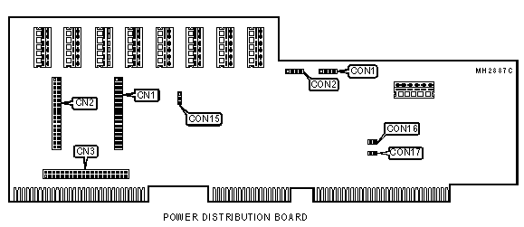
CONNECTIONS | |||
|
Purpose |
Location |
Purpose |
Location |
|
Temperature sensor interface |
CON1 |
Floppy drive interface |
cn2 |
|
Chassis fan power |
CON2 |
IDE interface |
cn3 |
|
Floppy drive interface |
cn1 | ||
|
USER CONFIGURABLE SETTINGS | |||
|
Function |
Jumper |
Position | |
|
» |
Floppy drives write protect disabled |
CON15 |
pins 1 & 2 closed |
|
Floppy drives write protect enabled |
CON15 |
pins 2 & 3 closed | |
|
» |
Factory configured - do not alter |
CON16 |
N/A |
|
» |
Factory configured - do not alter |
CON17 |
N/A |
|
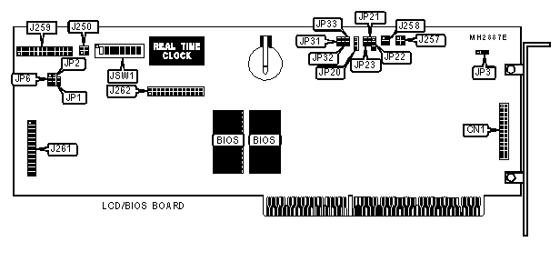
CONNECTIONS | |
|
Purpose |
Location |
|
LCD interface |
CN1 |
|
USER CONFIGURABLE SETTINGS | |||
|
Function |
Jumper |
Position | |
|
» |
Factory configured - do not alter |
JP1 |
Closed |
|
» |
INT 2 asymmetric |
JP2 |
pins 2 & 3 closed |
|
INT 2 symmetric |
JP2 |
pins 1 & 2 closed | |
|
» |
Safe operation enabled |
JP3 |
pins 2 & 3 closed |
|
Micro-switch override |
JP3 |
pins 1 & 2 closed | |
|
» |
INT ACK 2 asymmetric |
JP6 |
pins 2 & 3 closed |
|
INT ACK 2 symmetric |
JP6 |
pins 1 & 2 closed | |
|
» |
Keyboard/mouse lock set by key |
JP20 |
pins 1 & 2 closed |
|
Keyboard/mouse enabled |
JP20 |
pins 2 & 3 closed | |
|
Keyboard/mouse locked |
JP20 |
Open | |
|
» |
I/O CHK# disabled |
JP21 |
Open |
|
/O CHK# enabled |
JP21 |
Closed | |
|
» |
3-mode diskette primary address enabled |
JP22 |
pins 1 & 2 closed |
|
3-mode diskette secondary address enabled |
JP22 |
pins 2 & 3 closed | |
|
» |
VCCAUX 5v auxiliary enabled |
JP23 |
Open |
|
VCCAUX 5v auxiliary disabled |
JP23 |
Closed | |
|
» |
DCM COM port access, lower 64KB memory installed |
JP34 |
pins 2 & 3 closed |
|
DCM COM port access, upper 64KB memory installed |
JP34 |
pins 1 & 2 closed | |
|
» |
Factory configured - do not alter |
J250 |
N/A |
|
» |
Factory configured - do not alter |
J257 |
N/A |
|
» |
Factory configured - do not alter |
J258 |
N/A |
|
» |
Factory configured - do not alter |
J259 |
N/A |
|
USER CONFIGURABLE SETTINGS (CON’T) | |||
|
Function |
Jumper |
Position | |
|
» |
Factory configured - do not alter |
J261 |
N/A |
|
» |
Factory configured - do not alter |
J262 |
N/A |
|
» |
Factory configured - do not alter |
JSW1/1 |
N/A |
|
» |
Factory configured - do not alter |
JSW1/2 |
N/A |
|
» |
Factory configured - do not alter |
JSW1/3 |
N/A |
|
» |
Factory configured - do not alter |
JSW1/4 |
N/A |
|
» |
Factory configured - do not alter |
JSW1/5 |
N/A |
|
» |
RAM test enabled |
JSW1/6 |
Off |
|
RAM test disabled |
JSW1/6 |
On | |
|
» |
COM port speed set by ECU |
JSW1/7 |
Off |
|
COM1 = 9600, n, 8, 1 & COM2 = 2400, n, 8, 1 |
JSW1/7 |
On | |
|
» |
Password disabled |
JSW1/8 |
On |
|
Password enabled |
JSW1/8 |
Off | |
|
Note: The location of JP34 is unidentified. | |||
|
EISA MEMORY CONFIGURATION | |||
|
Setting |
JP31 |
JP32 |
JP33 |
|
1C000H - 1FFFFH |
pins 1 & 2 closed |
pins 1 & 2 closed |
pins 1 & 2 closed |
|
18000H - 1BFFFH |
pins 2 & 3 closed |
pins 1 & 2 closed |
pins 1 & 2 closed |
|
14000H - 17FFFH |
pins 1 & 2 closed |
pins 2 & 3 closed |
pins 1 & 2 closed |
|
10000H - 13FFFH |
pins 2 & 3 closed |
pins 2 & 3 closed |
pins 1 & 2 closed |
|
0C000H - 0FFFFH |
pins 1 & 2 closed |
pins 1 & 2 closed |
pins 2 & 3 closed |
|
08000H - 0BFFFH |
pins 2 & 3 closed |
pins 1 & 2 closed |
pins 2 & 3 closed |
|
04000H - 07FFFH |
pins 1 & 2 closed |
pins 2 & 3 closed |
pins 2 & 3 closed |
|
00000H - 03FFFH |
pins 2 & 3 closed |
pins 2 & 3 closed |
pins 2 & 3 closed |