PACKARD BELL
386-33
|
Processor |
80386DX |
|
Processor Speed |
33MHz |
|
Chip Set |
Intel |
|
Max. Onboard DRAM |
8MB |
|
SRAM Cache |
None |
|
BIOS |
Phoenix |
|
Dimensions |
355mm x 304mm |
|
I/O Options |
32-bit expansion slots (2), parallel port, serial ports (2) |
|
NPU Options |
80387DX |
|
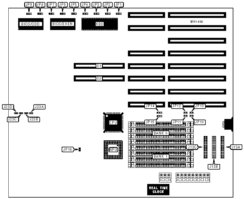
CONNECTIONS | |||
|
Purpose |
Location |
Purpose |
Location |
|
Parallel port |
J13A |
Reset switch |
J23B |
|
Serial port 1 (9 pin) |
J13B/pins 1-10 |
Speaker |
J23C |
|
Serial port 2 (9 pin) |
J13B/pins 11-20 |
Power LED & keylock |
J23D |
|
Serial port 2 (25 pin) |
J13C |
32-bit expansion slots |
S1 & S2 |
|
Reserved for future use |
J23A | ||
|
Note:J13C is a 25 pin version of serial port 2 (J13B pins 11-20). Either connector may be used, but not both. | |||
|
USER CONFIGURABLE SETTINGS | |||
|
Function |
Jumper |
Position | |
| » |
Monitor type select color |
JP5 |
pins 2 & 3 closed |
|
Monitor type select monochrome |
JP5 |
pins 1 & 2 closed | |
| » |
Keyboard reset disabled |
JP6 |
pins 2 & 3 closed |
|
Keyboard reset enabled |
JP6 |
pins 1 & 2 closed | |
| » |
NPU disabled |
JP7 |
pins 2 & 3 closed |
|
NPU enabled |
JP7 |
pins 1 & 2 closed | |
| » |
Printer acknowledge trailing edge |
JP8 |
pins 2 & 3 closed |
|
Printer acknowledge leading edge |
JP8 |
pins 1 & 2 closed | |
| » |
BIOS type select 2764 |
JP9 |
pins 1 & 2 closed |
|
BIOS type select 27128 |
JP9 |
pins 2 & 3 closed | |
| » |
Factory configured - do not alter |
JP16 |
Open |
|
SERIAL PORT 1 (J13B/PINS 1-10) CONFIGURATION | ||
|
Mode |
JP3 | |
| » |
Enabled (COM1) |
pins 1 & 2 closed |
|
Disabled |
pins 2 & 3 closed | |
|
SERIAL PORT 2 (J13B/PINS 11-20 OR J13C) CONFIGURATION | ||
|
Mode |
JP4 | |
| » |
Enabled (COM2) |
pins 1 & 2 closed |
|
Disabled |
pins 2 & 3 closed | |
|
PARALLEL PORT (J13A) CONFIGURATION | |||
|
LPT |
JP1 |
JP2 | |
| » |
LPT1 |
pins 1 & 2 closed |
pins 2 & 3 closed |
|
LPT2 |
pins 2 & 3 closed |
pins 1 & 2 closed | |
|
Disabled |
pins 2 & 3 closed |
pins 2 & 3 closed | |
|
DRAM CONFIGURATION | ||||||
|
Size |
Bank 0 |
Bank 1 |
JP11 |
JP12 |
JP14 |
JP15 |
|
1MB |
(4) 256K x 9 |
NONE |
Open |
Open |
pins 1 & 2 |
pins 1 & 2 |
|
2MB |
(4) 256K x 9 |
(4) 256K x 9 |
Closed |
Open |
pins 1 & 2 |
pins 1 & 2 |
|
4MB |
(4) 1M x 9 |
NONE |
Open |
Closed |
pins 2 & 3 |
pins 2 & 3 |
|
8MB |
(4) 1M x 9 |
(4) 1M x 9 |
Closed |
Closed |
pins 2 & 3 |
pins 2 & 3 |
|
Note:Pins designated should be in the closed position. | ||||||
|
RAM TYPE CONFIGURATION | |||
|
Type |
JP10 |
JP13 | |
|
RAS/CAS |
Open |
Open | |
| » |
Fast Paged |
Closed |
Closed |
|
Static Column |
Open |
Closed | |