TORONTO MICROELECTRONICS, INC.
TME2106
|
Processor |
Pentium |
|
Processor Speed |
75/90/100/120/133/150/166MHz |
|
Chip Set |
Intel |
|
Video Chip Set |
None |
|
Maximum Onboard Memory |
128MB (EDO supported) |
|
Maximum Video Memory |
None |
|
Cache |
256/512KB |
|
BIOS |
AMI |
|
Data Bus |
Integrated 32-bit PCI/ 16-bit ISA |
|
Dimensions |
Unidentified |
|
I/O Options |
Ethernet port, floppy drive interface, IDE interfaces (2), SCSI connector, parallel port, PS/2 mouse interface, serial ports (2), cache slot, temperature indicator connector, auxiliary connector, PC/104 connectors (2) |
|
NPU Options |
None |
|
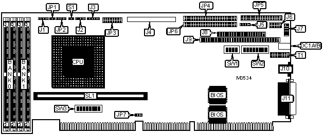
CONNECTIONS | |||
|
Purpose |
Location |
Purpose |
Location |
|
SCSI interface LED |
D1 |
PC/104 C & D connector |
J9 |
|
Network/LAN LED |
DC1A |
Ethernet port |
J10 |
|
Network/LAN LED |
DC1B |
Parallel port |
J11 |
|
Chassis fan power |
J1 |
Temperature indicator connector |
JP2 |
|
PS/2 mouse interface |
J2 |
Auxiliary connector |
JP3 |
|
Keyboard connector |
J3 |
IDE (44-pin) interface 1 |
JP4 |
|
SCSI wide 2 interface |
J4 |
Floppy drive interface |
JP5 |
|
External battery |
J5 |
IDE (44-pin) interface 2 |
JP6 |
|
Serial port 1 |
J6 |
Reset switch |
S1 |
|
Serial port 2 |
J7 |
Cache slot |
SL1 |
|
PC/104 A & B connector |
J8 | ||
|
Note: The location of D1 is unidentified. The orientation of DC1A & DC1B is unidentified. | |||
|
USER CONFIGURABLE SETTINGS | |||
|
Function |
Label |
Position | |
|
» |
CMOS memory normal operation |
JP1 |
Open |
|
CMOS memory clear |
JP1 |
Closed | |
|
» |
Factory configured - do not alter |
SW1/1 |
Unidentified |
|
» |
Factory configured - do not alter |
SW1/2 |
Unidentified |
|
» |
Factory configured - do not alter |
SW1/3 |
Unidentified |
|
Watchdog timer enabled |
SW2/1 |
On | |
|
Watchdog timer disabled |
SW2/1 |
Off | |
|
C800-CFFFF enabled |
SW2/4 |
On | |
|
C800-CFFFF disabled |
SW2/4 |
Off | |
|
D0000-D7FFF enabled |
SW2/5 |
On | |
|
D0000-D7FFF disabled |
SW2/5 |
Off | |
|
D8000-DFFFF enabled |
SW2/6 |
On | |
|
D8000-DFFFF disabled |
SW2/6 |
Off | |
|
PS/2 mouse enabled |
SW2/7 |
On | |
|
PS/2 mouse disabled |
SW2/7 |
Off | |
|
Monitor type select CGA |
SW2/8 |
On | |
|
Monitor type select monochrome/VGA |
SW2/8 |
Off | |
|
AUXCLK to backplane enabled |
SW3/1 |
On | |
|
AUXCLK to backplane disabled |
SW3/1 |
Off | |
|
AUXDATA to backplane enabled |
SW3/2 |
On | |
|
AUXDATA to backplane disabled |
SW3/2 |
Off | |
|
SWRST to backplane enabled |
SW3/3 |
On | |
|
SWRST to backplane disabled |
SW3/3 |
Off | |
|
VABT1 to backplane enabled |
SW3/4 |
On | |
|
VBAT1 to backplane disabled |
SW3/4 |
Off | |
|
KBCLK to backplane enabled |
SW3/5 |
On | |
|
KBCLK to backplane disabled |
SW3/5 |
Off | |
|
KBDATA to backplane enabled |
SW3/6 |
On | |
|
KBDATA to backplane disabled |
SW3/6 |
Off | |
|
SPKR OUTPUT to backplane enabled |
SW3/7 |
On | |
|
SPKR OUTPUT to backplane disabled |
SW3/7 |
Off | |
|
KBINH to backplane enabled |
SW3/8 |
On | |
|
KBINH to backplane disabled |
SW3/8 |
Off | |
|
Jumper information unavailable |
T1 |
Unidentified | |
|
Note: SW2/5 must be off for INT47 to be used. | |||
|
DRAM CONFIGURATION | ||
|
Size |
Bank 0 |
Bank 1 |
|
8MB |
(2) 1M x 36 |
None |
|
16MB |
(2) 2M x 36 |
None |
|
16MB |
(2) 1M x 36 |
(2) 1M x 36 |
|
24MB |
(2) 1M x 36 |
(2) 2M x 36 |
|
32MB |
(2) 4M x 36 |
None |
|
32MB |
(2) 2M x 36 |
(2) 2M x 36 |
|
40MB |
(2) 1M x 36 |
(2) 4M x 36 |
|
48MB |
(2) 2M x 36 |
(2) 4M x 36 |
|
64MB |
(2) 8M x 36 |
None |
|
64MB |
(2) 4M x 36 |
(2) 4M x 36 |
|
72MB |
(2) 1M x 36 |
(2) 8M x 36 |
|
80MB |
(2) 2M x 36 |
(2) 8M x 36 |
|
96MB |
(2) 4M x 36 |
(2) 8M x 36 |
|
128MB |
(2) 8M x 36 |
(2) 8M x 36 |
|
128MB |
(2) 16M x 36 |
None |
|
CACHE CONFIGURATION | |
|
Size |
SL2 |
|
256KB |
256KB module installed |
|
512KB |
512KB module installed |
|
CPU SPEED SELECTION | ||||||
|
CPU speed |
Clock speed |
Multiplier |
JP7 |
SW2/2 |
SW2/3 |
SW1/4 |
|
75MHz |
50MHz |
1.5x |
1 & 2 |
On |
On |
Off |
|
90MHz |
60MHz |
1.5x |
2 & 3 |
On |
Off |
Off |
|
100MHz |
66MHz |
1.5x |
2 & 3 |
Off |
On |
Off |
|
120MHz |
60MHz |
2x |
2 & 3 |
On |
Off |
On |
|
133MHz |
66MHz |
2x |
2 & 3 |
Off |
On |
On |
|
150MHz |
60MHz |
2.5x |
2 & 3 |
On |
Off |
On |
|
166MHz |
66MHz |
2.5x |
2 & 3 |
Off |
On |
On |
|
Note: Pins designated should be in the closed position. If 150MHz or 166MHz CPU is used, install R40 (0 Ohm) & R39 (10K). | ||||||
|
DIAGNOSTIC LED(S) | |||
|
LED |
Color |
Status |
Condition |
|
DC1A/B |
Green |
On |
UTP link is good |
|
DC1A/B |
Green |
Off |
LAN controller in AUI mode |
|
DC1A/B |
Red |
On |
LAN controller detects a collision in TPI mode |
|
DC1A/B |
Red |
Off |
No collision detected by LAN controller |