TORONTO MICROELECTRONICS, INC.
TME2003
|
Processor |
CS486DX/AM486DX/80486DX/CX486DX2/AM486DX2/80486DX2/ CX486DX4/AM486DX4/80486DX4/CX5X86/AM X5 |
|
Processor Speed |
25/33/40/50(internal)/50/66(internal)/75(internal)/80(internal)/ 100(internal)/120(internal)/133(internal)MHz |
|
Chip Set |
Unidentified |
|
Video Chip Set |
None |
|
Maximum Onboard Memory |
64MB (EDO supported) |
|
Maximum Video Memory |
None |
|
Cache |
256KB |
|
BIOS |
AMI |
|
Dimensions |
188mm x 122mm |
|
Data Bus |
Integrated 32-bit PCI/ 16-bit ISA |
|
I/O Options |
Ethernet 10Base5 connector, Ethernet 10BaseT connector, floppy drive interface, IDE interface, parallel port, serial ports (3), PC/104 connectors (2), flat panel connector, VGA port |
|
NPU Options |
None |
|
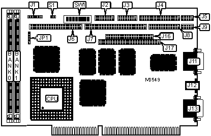
CONNECTIONS | |||
|
Purpose |
Location |
Purpose |
Location |
|
Power connector |
J1 |
Serial port 1 (shrouded header) |
J9 |
|
Auxiliary connector |
J2 |
Serial port 1 (DB9) |
J11 |
|
10Base5 network connector |
J3 |
10BaseT network connector |
J12 |
|
Floppy drive interface |
J4 |
VGA port |
J13 |
|
Serial port 2 |
J5 |
PC/104 A & B connector |
J16 |
|
IDE interface |
J6 |
PC/104 C & D connector |
J17 |
|
Flat panel connector |
J7 |
Chassis fan power |
JP1 |
|
Parallel port |
J8 |
Reset switch |
S1 |
|
USER CONFIGURABLE SETTINGS | |||
|
Function |
Label |
Position | |
|
PS/2 mouse enabled |
SW1/1 |
On | |
|
PS/2 mouse disabled |
SW1/1 |
Off | |
|
C000-C7FFFh enabled |
SW1/2 |
On | |
|
C000-C7FFFh disabled |
SW1/2 |
Off | |
|
C8000-CFFFFh enabled |
SW1/3 |
On | |
|
C8000-CFFFFh disabled |
SW1/3 |
Off | |
|
D0000-D7FFFh enabled |
SW1/4 |
On | |
|
D0000-D7FFFh disabled |
SW1/4 |
Off | |
|
D8000-DFFFFh enabled |
SW1/5 |
On | |
|
D8000-DFFFFh disabled |
SW1/5 |
Off | |
|
» |
Watchdog timer enabled |
SW1/8 |
On |
|
Watchdog timer disabled |
SW1/8 |
Off | |
|
DRAM CONFIGURATION | ||
|
Size |
Bank 0 |
Bank 1 |
|
1MB |
(1) 256K x 32 |
None |
|
2MB |
(1) 256K x 32 |
(1) 256K x 32 |
|
2MB |
(1) 512K x 32 |
None |
|
3MB |
(1) 256K x 32 |
(1) 512K x 32 |
|
4MB |
(1) 512K x 32 |
(1) 512K x 32 |
|
4MB |
(1) 1M x 32 |
None |
|
5MB |
(1) 256K x 32 |
(1) 1M x 32 |
|
6MB |
(1) 512K x 32 |
(1) 1M x 32 |
|
8MB |
(1) 1M x 32 |
(1) 1M x 32 |
|
8MB |
(1) 2M x 32 |
None |
|
9MB |
(1) 256K x 32 |
(1) 2M x 32 |
|
10MB |
(1) 512K x 32 |
(1) 2M x 32 |
|
12MB |
(1) 1M x 32 |
(1) 2M x 32 |
|
16MB |
(1) 2M x 32 |
(1) 2M x 32 |
|
16MB |
(1) 4M x 32 |
None |
|
17MB |
(1) 256K x 32 |
(1) 4M x 32 |
|
18MB |
(1) 512K x 32 |
(1) 4M x 32 |
|
20MB |
(1) 1M x 32 |
(1) 4M x 32 |
|
24MB |
(1) 2M x 32 |
(1) 4M x 32 |
|
32MB |
(1) 4M x 32 |
(1) 4M x 32 |
|
32MB |
(1) 8M x 32 |
None |
|
33MB |
(1) 256K x 32 |
(1) 8M x 32 |
|
34MB |
(1) 512K x 32 |
(1) 8M x 32 |
|
36MB |
(1) 1M x 32 |
(1) 8M x 32 |
|
DRAM CONFIGURATION (CON’T) | ||
|
Size |
Bank 0 |
Bank 1 |
|
40MB |
(1) 2M x 32 |
(1) 8M x 32 |
|
48MB |
(1) 4M x 32 |
(1) 8M x 32 |
|
64MB |
(1) 8M x 32 |
(1) 8M x 32 |
|
64MB |
(1) 16M x 32 |
None |
|
Note: Board accepts EDO memory. | ||
|
CACHE CONFIGURATION |
|
Note: 256KB cache is factory installed. The location is unidentified. |
|
CPU SPEED SELECTION | ||
|
Speed |
SW1/6 |
SW1/7 |
|
25MHz |
Off |
Off |
|
33MHz |
On |
Off |
|
40MHz |
Off |
On |
|
50iMHz |
Off |
Off |
|
50MHz |
On |
On |
|
66iMHz |
On |
Off |
|
75iMHz |
Off |
Off |
|
80iMHz |
Off |
On |
|
100iMHz |
On |
Off |
|
120iMHz |
Off |
On |
|
133iMHz |
On |
Off |
|
DIAGNOSTIC LED(S) | |||
|
LED |
Color |
Status |
Condition |
|
LED1 |
Yellow |
On |
UTP link is good |
|
LED1 |
Yellow |
Off |
LAN controller in AUI mode |
|
LED2 |
Red |
On |
LAN controller detects a collision in TPI mode |
|
LED2 |
Red |
Off |
No collision detected by LAN controller |
|
LED3 |
Red |
On |
Power (+5V) is on |
|
LED3 |
Red |
Off |
Power is off |
|
Note: LED1 and LED2 are located on bracket; the exact location is unidentified. LED3 is located above SIMM sockets on the component side of the card; the exact location is unidentified. | |||