TEKNOR INDUSTRIAL COMPUTERS, INC.
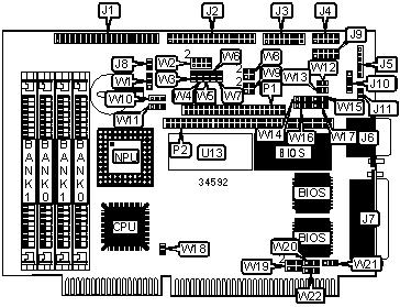
VIPER 804
|
Processor |
80386SX/CX486SLC/TI486SLC |
|
Processor Speed |
33MHz |
|
Chip Set |
Unidentified |
|
Video Chip Set |
None |
|
Maximum Onboard Memory |
16MB |
|
Maximum Video Memory |
None |
|
Cache |
512/1024KB |
|
BIOS |
Unidentified |
|
Dimensions |
Unidentified |
|
I/O Options |
Floppy drive interface, IDE interface, parallel port, PS/2 mouse interface, serial ports (3), PC/104 interfaces (2) |
|
NPU Options |
80387SX |
|
CONNECTIONS | |||
|
Purpose |
Location |
Purpose |
Location |
|
IDE interface |
J1 |
Parallel port |
J7 |
|
Floppy drive interface |
J2 |
External battery |
J8 |
|
Keyboard, speaker, reset, LED |
J3 |
Serial port 1 - internal |
J9 |
|
Serial port 2 |
J4 |
PS/2 mouse interface |
J10 |
|
Power connector |
J5 |
PC/104 connectors |
P1 & P2 |
|
Serial port 1 - external |
J6 | ||
|
USER CONFIGURABLE SETTINGS | |||
|
Function |
Label |
Position | |
|
» |
BIOS boot select normal boot |
J11 |
Open |
|
BIOS boot select emergency boot |
J11 |
Closed | |
|
External battery connected to J8 |
W1 |
Pins 1 & 2 closed | |
|
External battery connected to J5 |
W1 |
Pins 2 & 3 closed | |
|
» |
Power fail monitoring disabled |
W3 |
Open |
|
Power fail monitoring enabled |
W3 |
Closed | |
|
» |
IOCHRDY signal to IDE interface disabled |
W4 |
Open |
|
IOCHRDY signal to IDE interface enabled |
W4 |
Closed | |
|
» |
Watchdog timer enabled |
W5 |
Closed |
|
Watchdog timer disabled |
W5 |
Open | |
|
» |
Flash BIOS write enabled |
W6 |
Closed |
|
Flash BIOS write disabled |
W6 |
Open | |
|
» |
Flash disk write enabled |
W7 |
Closed |
|
Flash disk write disabled |
W7 |
Open | |
|
» |
Battery type select internal |
W10 |
Pins 1 & 2 closed |
|
Battery type select external |
W10 |
Pins 2 & 3 closed | |
|
» |
Power failure detection source external power fail (pin 6 on J5) |
W11 |
Pins 1 & 2 closed |
|
Power failure detection source internal/external battery <3v |
W11 |
Pins 2 & 3 closed | |
|
» |
SYSCLK select 8MHz (asynchronous) |
W18 |
Closed |
|
SYSCLK select programmed in BIOS setup (synchronous) |
W18 |
Open | |
|
» |
Parallel port IRQ select IRQ7 |
W20 |
Pins 2 & 3 closed |
|
Parallel port IRQ select IRQ5 |
W20 |
Pins 1 & 2 closed | |
|
SIMM CONFIGURATION | ||
|
Size |
Bank 0 |
Bank 1 |
|
1MB |
(2) 256K x 9 |
(2) 256K x 9 |
|
2MB |
(2) 1M x 9 |
None |
|
4MB |
(2) 1M x 9 |
(2) 1M x 9 |
|
8MB |
(2) 4M x 9 |
None |
|
16MB |
(2) 4M x 9 |
(2) 4M x 9 |
|
SOLID STATE DISK CONFIGURATION |
|
Note: To increase the size of the SSD, install upgrade in U13. |
|
DMA CHANNEL SELECTION | |||
|
Channel |
W21 |
W22 | |
| » |
None |
Open |
Open |
|
1 |
Pins 1 & 2 closed |
Pins 1 & 2 closed | |
|
3 |
Pins 2 & 3 closed |
Pins 2 & 3 closed | |
|
SERIAL PORT 2 LOOPBACK SELECTION | |||
|
Setting |
W12 |
W13 | |
| » |
Normal |
Open |
Open |
|
Loopback |
Closed |
Closed | |
|
SERIAL PORT 2 SELECTION | |||||
|
Setting |
W14 |
W15 |
W16 |
W17 | |
| » |
RS-232 |
Pins 1 & 2 closed |
Pins 1 & 2 closed |
Pins 1 & 2 closed |
Pins 1 & 2 closed |
|
RS-485 |
Pins 2 & 3 closed |
Pins 2 & 3 closed |
Pins 2 & 3 closed |
Pins 2 & 3 closed | |
|
FLOPPY DRIVE EDOUT SELECTION | ||
|
Setting |
W9 | |
| » |
Left to software |
Open |
|
Ground to pin 17 on J3 |
Pins 2 & 4 closed | |
|
Ground to pin 29 on J3 |
Pins 3 & 4 closed | |
|
EDOUT to pin 29 on J3 |
Pins 1 & 3 closed | |
|
EDOUT to pin 17 on J3 |
Pins 1 & 2 closed | |
|
FLOPPY DRIVE HDOUT SELECTION | ||
|
Setting |
W8 | |
| » |
Left to software |
Open |
|
Ground to pin 27 on J3 |
Pins 2 & 4 closed | |
|
Ground to pin 33 on J3 |
Pins 3 & 4 closed | |
|
HDOUT to pin 33 on J3 |
Pins 1 & 3 closed | |
|
HDOUT to pin 27 on J3 |
Pins 1 & 2 closed | |
|
BASE I/O SELECTION | ||
|
Address |
W19 | |
| » |
190H |
Pins 1 & 2, 3 & 4 closed |
|
290H |
Pins 1 & 2 closed | |
|
390H |
Pins 3 & 4 closed | |
|
390H |
Open | |
|
EXTENDED BIOS MODE SELECTION | ||
|
Setting |
W2 | |
|
VT100 |
Pins 5 & 6 closed | |
|
Serial download |
Pins 7 & 8 closed | |
| » |
Standard mode |
Pins 5 & 6 closed |
| » |
Normal mode |
Pins 7 & 8 closed |