UNIDENTIFIED
HP5-ISA-6A6B1
|
Processor |
Pentium |
|
Processor Speed |
60/66MHz |
|
Chip Set |
OPTI |
|
Max. Onboard DRAM |
128MB |
|
Cache |
64/128/256/512KB |
|
BIOS |
AMI |
|
Dimensions |
330mm x 218mm |
|
I/O Options |
32-bit VESA local bus slots (2) |
|
NPU Options |
None |
|
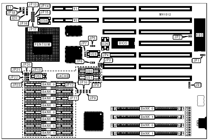
CONNECTIONS |
|||
|
Purpose |
Location |
Purpose |
Location |
|
External battery |
J9 |
Reset switch |
S1 |
|
Power LED & keylock |
J20 |
32-bit VESA local bus slot |
V1 |
|
Speaker |
JP18 |
32-bit VESA local bus slot |
V2 |
|
USER CONFIGURABLE SETTINGS |
|||
|
Function |
Jumper |
Position |
|
|
» |
CMOS memory normal operation (Internal Battery) |
JP1 |
pins 2 & 3 closed |
|
|
CMOS memory normal operation (External Battery) |
JP1 |
Open |
|
|
CMOS memory clear |
JP1 |
pins 1 & 2 closed |
|
» |
Monitor type select color |
JP2 |
Closed |
|
|
Monitor type select monochrome |
JP2 |
Open |
|
» |
Memory data inactive at end of last T2 |
JP3 |
Open |
|
|
Memory data inactive at beginning of last T2 |
JP3 |
Closed |
|
» |
I/O bus speed select 0 wait states |
JP10 |
Closed |
|
|
I/O bus speed select 1 wait state |
JP10 |
Open |
|
» |
Local bus select 0 wait states |
JP11 |
Closed |
|
|
Local bus select 1 wait state |
JP11 |
Open |
|
DRAM CONFIGURATION |
||
|
Size |
Bank 0 |
Bank 1 |
|
2MB |
(2) 256K x 36 |
NONE |
|
4MB |
(2) 256K x 36 |
(2) 256K x 36 |
|
4MB |
(2) 512K x 36 |
NONE |
|
6MB |
(2) 256K x 36 |
(2) 512K x 36 |
|
8MB |
(2) 512K x 36 |
(2) 512K x 36 |
|
8MB |
(2) 1M x 36 |
NONE |
|
10MB |
(2) 256K x 36 |
(2) 1M x 36 |
|
12MB |
(2) 512K x 36 |
(2) 1M x 36 |
|
16MB |
(2) 1M x 36 |
(2) 1M x 36 |
|
16MB |
(2) 2M x 36 |
NONE |
|
18MB |
(2) 256K x 36 |
(2) 2M x 36 |
|
20MB |
(2) 512K x 36 |
(2) 2M x 36 |
|
24MB |
(2) 1M x 36 |
(2) 2M x 36 |
|
32MB |
(2) 2M x 36 |
(2) 2M x 36 |
|
32MB |
(2) 4M x 36 |
NONE |
|
34MB |
(2) 256K x 36 |
(2) 4M x 36 |
|
36MB |
(2) 512K x 36 |
(2) 4M x 36 |
|
40MB |
(2) 1M x 36 |
(2) 4M x 36 |
|
48MB |
(2) 2M x 36 |
(2) 4M x 36 |
|
64MB |
(2) 4M x 36 |
(2) 4M x 36 |
|
64MB |
(2) 8M x 36 |
NONE |
|
66MB |
(2) 256K x 36 |
(2) 8M x 36 |
|
68MB |
(2) 512K x 36 |
(2) 8M x 36 |
|
72MB |
(2) 1M x 36 |
(2) 8M x 36 |
|
80MB |
(2) 2M x 36 |
(2) 8M x 36 |
|
96MB |
(2) 4M x 36 |
(2) 8M x 36 |
|
128MB |
(2) 8M x 36 |
(2) 8M x 36 |
|
CACHE CONFIGURATION |
|||||
|
Size |
Bank 0 |
Bank 1 |
TAG (U30) |
TAG (U31) |
Dirty Bit (U52) |
|
64KB |
(8) 8K x 8 |
NONE |
NONE |
8K x 8 |
(1) 16K x 1 |
|
128KB |
(8) 8K x 8 |
(8) 8K x 8 |
NONE |
8K x 8 |
(1) 16K x 1 |
|
256KB |
(8) 32K x 8 |
NONE |
NONE |
8K x 8 |
(1) 16K x 1 |
|
512KB |
(8) 32K x 8 |
(8) 32K x 8 |
8K x 8 |
8K x 8 |
(1) 16K x 1 |
|
CACHE JUMPER CONFIGURATION |
||||||
|
Size |
JP6 |
JP19 |
JP20 |
JP21 |
JP22 |
JP23 |
|
64KB |
pins 1 & 2 |
Open |
Open |
Open |
pins 1 & 2 |
pins 1 & 2 |
|
128KB |
pins 2 & 3 |
Closed |
Open |
Open |
pins 2 & 3 |
pins 2 & 3 |
|
256KB |
pins 1 & 2 |
Closed |
Closed |
Open |
pins 1 & 2 |
pins 1 & 2 |
|
512KB |
pins 2 & 3 |
Closed |
Closed |
Closed |
pins 2 & 3 |
pins 2 & 3 |
|
Note: Pins designated should be in the closed position. |
||||||
|
VESA MODE CONFIGURATION |
|
|
Setting |
JP12 |
|
Enabled |
Closed |
|
Disabled |
Open |
|
VESA ID0 & ID1 CONFIGURATION |
||
|
Setting |
JP13 (ID0) |
JP14 (ID1) |
|
80386 |
Open |
Closed |
|
80486 |
Closed |
Open |
|
VESA ID2 CONFIGURATION |
|
|
VESA wait states |
JP15 (ID2) |
|
0 wait states |
Open |
|
1 wait state |
Closed |
|
VESA ID3 CONFIGURATION |
|
|
Speed |
JP16 (ID3) |
|
£ 33MHz |
Open |
|
> 33MHz |
Closed |
|
VESA ID4 CONFIGURATION |
|
|
Setting |
JP17 (ID4) |
|
Reserved for future use |
Closed |
|
SYSTEM CLOCK CONFIGURATION |
||||
|
LCLK |
U28 |
JP4 |
JP5 |
JP7 |
|
Internal |
Empty |
Open |
pins 2 & 3 closed |
pins 2 & 3 closed |
|
External |
Installed |
Closed |
pins 1 & 2 closed |
pins 1 & 2 closed |
|
Note: When LCLK is derived internally, LCLK is 1/2 of the CPU clock (U38). When LCLK is derived from an external source (U28), LCLK is equal to the oscillator speed. |
||||
|
LCLK TO ATCLK DIVISION CONFIGURATION |
||||
|
LCLK Frequency |
LCLK Divisor |
ATLCK result |
JP8 |
JP9 |
|
16 to 20 MHz |
LCLK/2 |
8 to 10 MHz |
Closed |
Closed |
|
20 to 25 MHz |
LCLK/3 |
6.6 to 8.33 MHz |
Open |
Closed |
|
33 MHz |
LCLK/4 |
8.33 MHz |
Closed |
Open |
|
40 to 50 MHz |
LCLK/5 |
8 to 10 MHz |
Open |
Open |