ZEOS INTERNATIONAL, LTD.
PANTERA PENTIUM
|
Processor |
Pentium |
|
Processor Speed |
75/90/100/120/133/150MHz |
|
Chip Set |
VLSI |
|
Max. Onboard DRAM |
384MB |
|
Cache |
256/512KB (on external cache card) |
|
BIOS |
Unidentified |
|
Dimensions |
330mm x 218mm |
|
I/O Options |
Parallel port, serial ports (2), Infrared COM port, 32-bit PCI slots (3), floppy drive interface, IDE interfaces (2), SCSI interface, 10-baseT connector, 10-base2 connector, Legacy connector, VRM connector, cache slot |
|
NPU Options |
None |
|
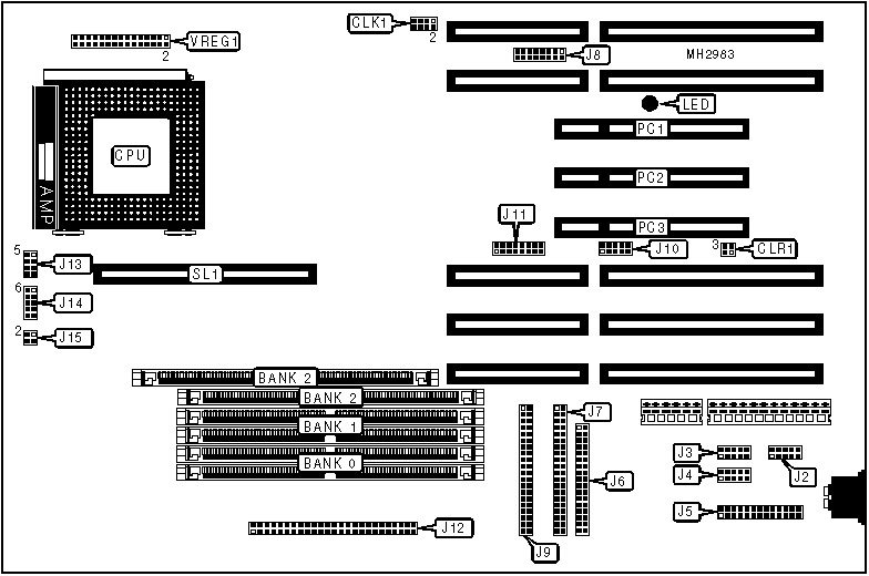
CONNECTIONS | |||
|
Purpose |
Location |
Purpose |
Location |
|
Serial port 1 |
J2 |
10-base2 connector |
J11 |
|
IR COM connector |
J3 |
SCSI connector |
J12 |
|
Serial port 2 |
J4 |
IDE interface LED |
J13 pins 1 & 2 |
|
Parallel port |
J5 |
Speaker |
J13 pins 5 - 9 |
|
Floppy drive interface |
J6 |
Power LED & keylock |
J14 pins 6 - 10 |
|
IDE interface 2 |
J7 |
Reset switch |
J15 pins 2 & 4 |
|
Legacy connector |
J8 |
32-bit PCI slots |
PC1 - PC3 |
|
IDE interface 1 |
J9 |
External cache card |
SL1 |
|
10-baseT connector |
J10 |
VRM connector |
VREG1 |
|
USER CONFIGURABLE SETTINGS | |||
|
Function |
Jumper |
Position | |
|
» |
AMD LAN or LAN/SCSI chip not installed |
CLK1 |
pins 7 & 8 open |
|
AMD LAN or LAN/SCSI chip installed |
CLK1 |
pins 7 & 8 closed | |
|
» |
Flash BIOS write protect enabled |
CLR1 |
pins 1 & 2 closed |
|
Flash BIOS write protect disabled |
CLR1 |
pins 3 & 4 closed | |
|
DRAM CONFIGURATION | |||
|
Size |
Bank 0 |
Bank 1 |
Bank 2 |
|
2MB |
(2) 256K x 36 |
NONE |
NONE |
|
4MB |
(2) 256K x 36 |
(2) 256K x 36 |
NONE |
|
8MB |
(2) 1M x 36 |
NONE |
NONE |
|
10MB |
(2) 1M x 36 |
(2) 256K x 36 |
NONE |
|
12MB |
(2) 512K x 36 |
(2) 512K x 36 |
(2) 512K x 36 |
|
16MB |
(2) 1M x 36 |
(2) 1M x 36 |
NONE |
|
24MB |
(2) 1M x 36 |
(2) 1M x 36 |
(2) 1M x 36 |
|
32MB |
(2) 2M x 36 |
(2) 2M x 36 |
NONE |
|
64MB |
(2) 4M x 36 |
(2) 4M x 36 |
NONE |
|
128MB |
(2) 8M x 36 |
(2) 8M x 36 |
NONE |
|
256MB |
(2) 16M x 36 |
(2) 16M x 36 |
NONE |
|
384MB |
(2) 16M x 36 |
(2) 16M x 36 |
(2) 16M x 36 |
|
CACHE CONFIGURATION | |
|
Size |
SL1 |
|
256KB |
256KB cache card installed |
|
512KB |
512KB cache card installed |
|
CPU SPEED CONFIGURATION | |
|
Speed |
CLK1 |
|
75MHz |
pins 5 & 6, 7 & 8 closed |
|
90MHz |
pins 7 & 8 closed |
|
100MHz |
pins 5 & 6 closed |
|
120MHz |
pins 1 & 2, 7 & 8 closed |
|
133MHz |
pins 1 & 2, 5 & 6 closed |
|
150MHz |
pins 1 & 2, 3 & 4, 7 & 8 closed |
|
Note: The settings provided above apply to part numbers 010-0066-03, 010-0066-17, and 010-0066-18 only. Using these settings on boards with other part numbers may cause the system to lock up. See the following table for settings used by boards with other part numbers. | |
|
CPU SPEED CONFIGURATION | |
|
Speed |
CLK1 |
|
75MHz |
pins 1 & 2, 5 & 6 closed |
|
90MHz |
pins 5 & 6 closed |
|
100MHz (bus 66MHz) |
pins 1 & 2 closed |
|
100MHz (bus 50MHz) |
pins 1 & 2, 3 & 4, 5 & 6 closed |
|
120MHz |
pins 3 & 4, 5 & 6 closed |
|
133MHz |
pins 1 & 2, 3 & 4 closed |
|
DIAGNOSTIC LED | ||
|
LED |
Color |
Function |
|
On |
Red |
Power good signal is enabled |
|
Off |
Red |
Power good signal is disabled |