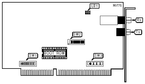
MADGE NETWORKS, LTD.
SMART 16/4 FIBER AT RINGNODE
|
NIC Type |
Token Ring |
|
Transfer Rate |
4/16Mbps |
|
Data Bus |
16-bit ISA |
|
Topology |
Ring |
|
Wiring Type |
62.5/125m m multimode graded index optical fiber |
|
Boot ROM |
Available |
|
ADDRESS SELECT |
||||
|
I/O Address |
Base Memory Address |
SW2/1 |
SW2/2 |
|
|
» |
0A20 - 0A2Fh |
CC000 - CDFFFh |
On |
On |
|
|
1A20 - 1A2Fh |
DC000 - DFFFFh |
Off |
On |
|
|
2A20 - 2A2Fh |
CE000 - CFFFFh |
On |
Off |
|
|
3A20 - 3A2Fh |
DE000 - DFFFFh |
Off |
Off |
|
AT BUS TIMING COMPATIBILITY |
||
|
Setting |
SW2/6 |
|
|
» |
Normal |
On |
|
|
Alternate |
Off |
|
BOOT ROM |
||
|
Setting |
SW2/3 |
|
|
» |
Disabled |
Off |
|
|
Enabled |
On |
|
BUS MASTER DMA |
||
|
Setting |
SW2/4 |
|
|
» |
Enabled |
On |
|
|
Disabled |
Off |
|
CLOCK SOURCE |
||
|
Setting |
SW2/7 |
|
|
» |
Asynchronous |
Off |
|
|
Synchronous |
On |
|
CONCENTRATOR TYPE |
||
|
Setting |
LB1 |
|
|
» |
802.5J |
|
|
|
Local wrap |
|
Note: Concentrator type is determined by placing a link block over the LB1 jumper block. The block has an arrow printed on the front and should resemble the diagram shown above. |
||
|
DATA TRANSFER RATE |
||
|
Speed |
SW2/8 |
|
|
» |
16Mbps |
Off |
|
|
4Mbps |
On |
|
DMA CONFIGURATION |
||
|
DMA |
SW3 |
|
|
» |
5 |
Position 3 |
|
|
1 |
Position 1 |
|
|
3 |
Position 2 |
|
|
6 |
Position 4 |
|
Note: Switch 3 is a four-position slide switch. Each position should be silk-screened on the switch itself. |
||
|
8/16 BIT MODE |
||
|
Setting |
SW2/5 |
|
|
» |
8/16-bit mode |
On |
|
|
Force 8-bit mode |
Off |
|
INTERRUPT SELECT |
||
|
IRQ |
SW1 |
|
|
» |
IRQ3 |
Position 7 |
|
|
IR/FONT |
Position 8 |
|
|
IRQ5 |
Position 6 |
|
|
IRQ7 |
Position 5 |
|
|
IRQ10 |
Position 4 |
|
|
IRQ11 |
Position 3 |
|
|
IRQ12 |
Position 2 |
|
|
IRQ15 |
Position 1 |
|
Note: Switch 1 is an eight-position slide switch. Each position should be silk-screened on the switch itself. |
||
|
CONNECTIONS |
|
|
Purpose |
Location |
|
Fiber-optic transmitter |
Tx |
|
Fiber-optic receiver |
Rx |