BOCA RESEARCH, INC.
BOCAMODEM M144IW
|
Modem Type |
Data (synchronous/asynchronous)/Fax |
|
Maximum Data Rate |
14.4Kbps |
|
Maximum Fax Rate |
9600bps |
|
Data Bus |
8-bit ISA |
|
Fax Class |
Class I & II |
|
Data Modulation Protocol |
Bell 103A/212A ITU-T V.21, V.22, V.22bis, V.23, V.32, V.32bis |
|
Fax Modulation Protocol |
ITU-T V.21CH2, V.27ter, V.29 |
|
Error Correction/Compression |
MNP5, V.42, V.42bis |
|
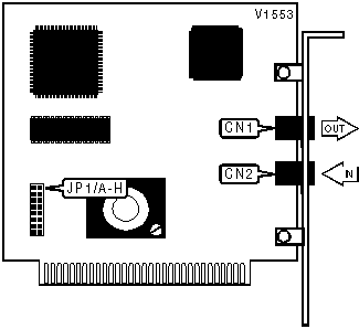
CONNECTIONS | |||
|
Purpose |
Location |
Purpose |
Location |
|
Line out |
CN1 |
Line in |
CN2 |
|
BASE I/O ADDRESS SELECTION | ||||
|
Port |
JP1/A |
JP1/B |
JP1/C |
JP1/D |
| » COM1: (3F8h) |
Closed |
Open |
Open |
Open |
| COM2: (2F8h) |
Open |
Closed |
Open |
Open |
| COM3: (3E8h) |
Open |
Open |
Closed |
Open |
| COM4: (2E8h) |
Open |
Open |
Open |
Closed |
|
INTERRUPT SELECTION | ||||
|
IRQ |
JP1/E |
JP1/F |
JP1/G |
JP1/H |
| 3 |
Closed |
Open |
Open |
Open |
| » 4 |
Open |
Closed |
Open |
Open |
| 5 |
Open |
Open |
Closed |
Open |
| 7 |
Open |
Open |
Open |
Closed |
Proprietary AT Command Set
|
AUTO-RETRAIN - FALLBACK/FALLFORWARD | |
|
Type: |
Configuration |
|
Format: |
AT [cmds] %En [cmds] |
|
Example: |
AT %E1 <CR> |
|
Description: |
Controls auto-retrain mode and fallback/fall forward. |
| Command |
Function |
| » %E0 |
Auto-retrain disabled. |
| %E1 |
Auto-retrain enabled. |
| %E2 |
Fallback/fall forward enabled. |
|
BIT-MAPPED REGISTERS | |
|
Registers |
Default |
|
S14 |
170 |
|
S21 |
0 |
|
S22 |
117 |
|
S23 |
7 |
|
S27 |
9 |
|
S28 |
Unidentified |
|
S31 |
Unidentified |
|
S39 |
Unidentified |
|
S40 |
Unidentified |
|
S41 |
Unidentified |
|
BREAK SEND | |
|
Type: |
Configuration |
|
Format: |
AT [cmds] \Bn [cmds] |
|
Example: |
AT \B3 <CR> |
|
Default: |
3 |
|
Range: |
1-9 |
|
Unit: |
.1 second |
|
Description: |
Sends break to modem. |
|
BREAK TYPE | ||||
|
Type: |
Configuration | |||
|
Format: |
AT [cmds] \Kn [cmds] | |||
|
Example: |
AT \K1 <CR> | |||
|
Description: |
Configures action of break signal. | |||
|
Command |
Break from DTE MNP/Normal mode |
Break from DTE Direct mode |
Break from remote modem | |
| \K0 |
Enter command mode, do not send break to remote modem. |
Send break to remote modem immediately, then enter command mode. |
Buffers cleared and break sent to DTE. | |
| \K1 |
Buffers cleared and break sent to remote modem. |
Send break to remote modem immediately, then enter command mode. |
Buffers cleared and break sent to DTE. | |
| \K2 |
Enter command mode, do not send break to remote modem. |
Send break to remote modem immediately. |
Send break to DTE immediately. | |
| \K3 |
Send break to remote modem immediately. |
Send break to remote modem immediately, then enter command mode. |
Send break to DTE immediately. | |
| \K4 |
Enter command mode, do not send break to remote modem. |
Send break to remote modem immediately. |
Break sent with received data to the DTE. | |
| » \K5 |
Send break with transmitted data. |
Send break to remote modem immediately. |
Break sent with received data to the DTE. | |
|
COMPRESSION | |
|
Type: |
Configuration |
|
Format: |
AT [cmd] %Cn [cmd] |
|
Example: |
AT \N2 %C1 \K5 <CR> |
|
Description: |
Selects data compression. |
| Command |
Function |
| %C0 |
Data compression disabled. |
| %C1 |
MNP5 enabled. |
| %C2 |
V.42bis enabled. |
| » %C3 |
MNP5 and V.42bis enabled. |
|
CONNECT MODE | |
|
Type: |
Configuration |
|
Format: |
AT [cmds] \Nn [cmds] |
|
Example: |
AT \N1 DT555-1212 <CR> |
|
Description: |
Sets connect mode. |
| Command |
Function |
|
\N0 |
Normal mode enabled. |
|
\N1 |
Direct mode enabled. |
|
\N2 |
Reliable mode enabled. |
|
\N3 |
Auto-reliable mode enabled, MNP mode with fallback to Normal mode. |
|
\N4 |
LAPM error-correction mode enabled. |
|
\N5 |
MNP error-correction mode enabled. |
|
FAX TRANSMIT LEVEL | |
|
Type: |
Register |
|
Format: |
AT [cmds] S92=n [cmds] |
|
Example: |
ATS92=10 <CR> |
|
Default: |
10 |
|
Range: |
1-15 |
|
Unit: |
-1dBm |
|
Description: |
Controls fax transmission level. |
|
FLOW CONTROL | |
|
Type: |
Configuration |
|
Format: |
AT [cmds] \Gn [cmds] |
|
Example: |
AT \G1 &K3 <CR> |
|
Description: |
Selects modem port flow control. |
|
Command |
Function |
| » \G0 |
Flow control disabled. |
| \G1 |
Flow control enabled. |
|
FLOW CONTROL CHARACTER - XOFF | |
|
Type: |
Register |
|
Format: |
AT [cmds] S33=n [cmds] |
|
Example: |
ATS33=19 <CR> |
|
Default: |
19 |
|
Range: |
0-255 |
|
Unit: |
ASCII |
|
Description: |
Sets the character used to represent XOFF. |
|
FLOW CONTROL CHARACTER - XON | |
|
Type: |
Register |
|
Format: |
AT [cmds] S32=n [cmds] |
|
Example: |
ATS32=17 <CR> |
|
Default: |
17 |
|
Range: |
0-255 |
|
Unit: |
ASCII |
|
Description: |
Sets the character used to represent XON. |
|
LINE SIGNAL LEVEL | |
|
Type: |
Configuration |
|
Format: |
AT [cmds] %L [cmds] |
|
Example: |
AT %L &W <CR> |
|
Default: |
Unidentified |
|
Range: |
9-43 |
|
Unit: |
-1 dBm |
|
Description: |
Returns received line signal level. |
|
MAXIMUM BLOCK SIZE FOR TRANSMISSION | |
|
Type: |
Configuration |
|
Format: |
AT [cmds] \An [cmds] |
|
Example: |
AT \A1 %C1 <CR> |
|
Description: |
Sets the maximum transmittable block size. |
| Command |
Function |
| \A0 |
MNP block size is 64 characters. |
| » \A1 |
MNP block size is 128 characters. |
| \A2 |
MNP block size is 192 characters. |
| \A3 |
MNP block size is 256 characters. |
|
MNP STREAM/BLOCK MODE | |
|
Type: |
Configuration |
|
Format: |
AT [cmds] \Ln [cmds] |
|
Example: |
AT \L1 DT555-1212 <CR> |
|
Description: |
Selects the transfer mode for MNP. |
| Command |
Function |
| » \L0 |
Stream mode for MNP enabled. |
| \L1 |
Block mode for MNP enabled. |
|
MNP10 LINK NEGOTIATION | |
|
Type: |
Configuration |
|
Format: |
AT [cmds] *Hn [cmds] |
|
Example: |
AT *H0 \W1 <CR> |
|
Description: |
Sets the speed at which MNP10 link negotiation will occur. |
| Command |
Function |
| » *H0 |
Link will be negotiated at highest possible speed. |
| *H1 |
Link will be negotiated at 1200bps. |
|
PSTN TRANSMIT LEVEL | |
|
Type: |
Register |
|
Format: |
AT [cmds] S91=n [cmds] |
|
Example: |
ATS91=10 <CR> |
|
Default: |
10 |
|
Range: |
1-15 |
|
Unit: |
-1dBm |
|
Description: |
Controls PSTN transmission level. |
|
REPORT SIGNAL QUALITY | |
|
Type: |
Configuration |
|
Format: |
AT [cmds] %Q [cmds] |
|
Example: |
AT %Q &W <CR> |
|
Range: |
0-255 |
|
Description: |
Reports signal quality. |
|
Note: A value of 8 or greater retrain enabled, only when %E1 is enabled. | |
|
SLEEP TIMER | |
|
Format |
AT [cmds] S24=n [cmds] |
|
Example: |
ATS24=0 <CR> |
|
Default: |
0 |
|
Range: |
0 - 255 |
|
Unit: |
1 second |
|
Description: |
Maximum duration of DTE and DCE inactivity allowed prior to initiating low-power sleep mode. |
|
TEST MODES | |||
|
Format |
AT [cmds] S16=n [cmds] | ||
|
Example: |
ATS16=128 <CR> | ||
|
Default: |
128 | ||
|
Range: |
0 - 255 | ||
|
Unit: |
Bit-mapped | ||
|
Description: |
Select type of loopback test. | ||
|
Bit |
Value |
Function | |
|
0 | 0 1 |
Local analog loopback test not in progress. Local analog loopback test in progress. | |
|
1 | 0 1 |
Remote analog loopback test not in progress. Remote analog loopback test in progress. | |
|
2 | 0 1 |
Local digital loopback test not in progress. Local digital loopback test in progress. | |
|
3 | 0 1 |
Remotely requested remote digital loopback test not in progress. Remotely requested remote digital loopback test in progress. | |
|
4 | 0 1 |
Locally requested remote digital loopback test not in progress. Locally requested remote digital loopback test in progress. | |
|
5 | 0 1 |
Remote digital loopback with local self-test not in progress. Remote digital loopback with local self-test in progress. | |
|
6 | 0 1 |
Local analog loopback with local self-test not in progress. Local analog loopback with local self-test in progress. | |
|
7 | 0 » 1 |
Remote analog loopback with local self-test not in progress. Remote analog loopback with local self-test in progress. | |
|
V.23 DIRECTION CONTROL | |
|
Type: |
Configuration |
|
Format: |
AT [cmds] %Fn [cmds] |
|
Example: |
AT %F1 &W <CR> |
|
Description: |
Controls the direction of transmit/receive 75/1200bps, only when \W1 is selected. |
| Command |
Function |
| %F0 |
75bps transmit/1200bps receive enabled. |
| » %F1 |
1200bps transmit/75bps receive enabled. |
|
V.23 SPLIT BAUD MODE | |
|
Type: |
Configuration |
|
Format: |
AT [cmds] \Wn [cmds] |
|
Example: |
AT \W1 <CR> |
|
Description: |
Controls V.23 split baud mode. |
| Command |
Function |
| » \W0 |
V.23 split baud mode disabled. |
| \W1 |
V.23 split baud mode enabled. |