APACHE MICRO PERIPHERALS, INC.
SEVEL V34I-V+/C, SEVEL V34IV-SP+/C
|
Card Type |
Modem (asynchronous) |
|
Chip Set |
Cirrus Logic |
|
I/O Options |
Speakerphone (Sevel V34IV-SP+/C only), voice |
|
Maximum Data Rate |
33.6Kbps |
|
Maximum Fax Rate |
14.4Kbps |
|
Data Bus |
16-bit ISA |
|
Fax Class |
Class I |
|
Data Modulation Protocol |
ITU-T V.32bis, V.34 U.S. Robotics x2 Rockwell V.FC |
|
Fax Modulation Protocol |
Unidentified |
|
Error Correction/Compression |
MNP5, V.42, V.42bis |
|
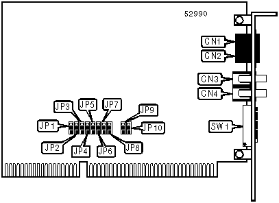
CONNECTIONS | ||||||
|
Function |
Label |
Function |
Label | |||
|
Line in |
CN1 |
Unidentified |
CN3 | |||
|
Line out |
CN2 |
Unidentified |
CN4 | |||
|
USER CONFIGURABLE SETTINGS | ||
|
Setting |
Label |
Position |
|
í Factory configured - do not alter |
SW1/7 |
Unidentified |
|
í Factory configured - do not alter |
SW1/8 |
N/A |
Note: SW1/8 may not be present on all models. | ||
|
SERIAL PORT ADDRESS SELECTION | ||
|
Setting |
SW1/5 |
SW1/6 |
|
3F8h (COM1:) |
On |
On |
|
2F8h (COM2:) |
Off |
On |
|
3E8h (COM3:) |
On |
Off |
|
í 2E8h (COM4:) |
Off |
Off |
|
INTERRUPT SELECTION | ||||
|
Setting |
SW1/1 |
SW1/2 |
SW1/3 |
SW1/4 |
|
í IRQ3 |
Off |
Off |
Off |
On |
|
IRQ4 |
Off |
Off |
On |
Off |
|
IRQ5 |
Off |
On |
Off |
Off |
|
IRQ7 |
On |
Off |
Off |
Off |
|
PLUG-N-PLAY SELECTION | |||||
|
Setting |
JP1 |
JP2 |
JP3 |
JP4 |
JP5 |
|
í Disabled |
Pins 1 & 2 |
Pins 1 & 2 |
Pins 1 & 2 |
Pins 1 & 2 |
Pins 1 & 2 |
|
Enabled |
Pins 2 & 3 |
Pins 2 & 3 |
Pins 2 & 3 |
Pins 2 & 3 |
Pins 2 & 3 |
|
PLUG-N-PLAY SELECTION (CON’T) | |||||
|
Setting |
JP6 |
JP7 |
JP8 |
JP9 |
JP10 |
|
í Disabled |
Pins 1 & 2 |
Pins 1 & 2 |
Pins 1 & 2 |
Pins 1 & 2 |
Pins 1 & 2 |
|
Enabled |
Pins 2 & 3 |
Pins 2 & 3 |
Pins 2 & 3 |
Pins 2 & 3 |
Pins 2 & 3 |
Note: SW1/1 through SW1/8 must all be off in Plug-N-Play mode. | |||||
|
SUPPORTED STANDARD COMMANDS |
|
Basic AT Commands |
|
+++, ‘comma’, A/ |
|
A, D, E, F, H, L, M, N, O, Q, V, W, X, Y, Z |
|
&C, &D, &F, &G, &J, &K, &P, &S, &T, &W, &Y, &Z |
|
Extended AT Commands |
|
\A, \B, \C, \G, \J, \N, \O, \Q, \T, \U, \X, \Y, \Z |
|
%A, %C, %E, %G, %L, %Q |
|
Special AT Commands |
|
-J, "H, +MS, "O |
|
S-Registers |
|
S0, S1, S2, S3, S4, S5, S6, S7, S8, S9, S10, S11, S12, S14, S16, S18, S21, S22, S23, S25, S30 |
Note: See MHI documentation for complete information. |
Proprietary AT Command Set
|
BIT-MAPPED REGISTER S27 | ||
|
Format |
AT [cmds] S27=n [cmds] | |
|
Default: |
0 | |
|
Range: |
0 - 224 | |
|
Unit: |
Bit-mapped | |
|
Description: |
Selects synchronous/asynchronous mode, line type, clock source, and ITU-T/Bell modes. | |
|
Bit |
Value |
Function |
|
3 - 0 |
0000 |
Not used. |
|
5, 4 |
í 0001 10 |
Local modem generates transmit clock source. Local DTE generates transmit clock source. Remote DCE/DTE generates transmit clock source. |
|
7, 6 |
í 0001 10 11 |
Use ITU-T V.22 at 300 or 1200bps Use Bell 212A at 300 or 1200bps Use ITU-T V.23 at 75/1200bps. Use ITU-T V.23 at 1200/75bps. |
|
BIT-MAPPED REGISTER S31 | |||||
|
Format: |
AT [cmds] S31=n [cmds] | ||||
|
Default: |
Unidentified | ||||
|
Range: |
0 - 59 | ||||
|
Description: | |||||
|
Bit |
Value |
Function | |||
|
0 |
0 í 1 |
Auto-mode detection disabled. In originate mode, handshake begins at line speed designated by the S37 register. Modem can shift to a slower speed if necessary. In answer mode, handshake attempted with the following protocols in order - V.FC, V.32bis, V.32, V.22bis, V.22 or Bell 212, V.21, and Bell 103. | |||
|
1 |
0 1 |
Trellis coding disabled. Trellis coding enabled. | |||
|
2 |
0 |
Not used. | |||
|
3 |
í 01 |
Calling tone disabled. 1300Hz calling tone enabled. | |||
|
4 |
í 01 |
Auto-retrain disabled. Auto-retrain enabled. | |||
|
5 |
0 1 |
Auto-fallback/fall-forward disabled. Auto-fallback/fall-forward enabled. | |||
|
BREAK TYPE | |||||
|
Type: |
Configuration | ||||
|
Format: |
AT [cmds] \Kn [cmds] | ||||
|
Description: |
Configures action of break signal. | ||||
|
Command |
Break from DTE Reliable/Normal mode |
Break from DTE Direct mode |
Modem receives \B |
Break from remote modem | |
|
\K0 |
Enter command mode, do not send break to remote modem. |
Send break to remote modem immediately, then enter command mode. |
Buffers cleared and break sent to remote modem. |
Buffers cleared and break sent to DTE. | |
|
\K1 |
Buffers cleared and break sent to remote modem. |
Send break to remote modem immediately. |
Buffers cleared and break sent to remote modem. |
Buffers cleared and break sent to DTE. | |
|
\K2 |
Enter command mode, do not send break to remote modem. |
Send break to remote modem immediately, then enter command mode. |
Send break to remote modem immediately. |
Send break to DTE immediately. | |
|
\K3 |
Send break to remote modem immediately. |
Send break to remote modem immediately. |
Send break to remote modem immediately. |
Send break to DTE immediately. | |
|
\K4 |
Enter command mode, do not send break to remote modem. |
Send break to remote modem immediately, then enter command mode. |
Send break to remote modem with transmitted data. |
Break sent with received data to the DTE. | |
|
\K5 |
Send break with transmitted data. |
Send break to remote modem immediately. |
Send break to remote modem with transmitted data. |
Break sent with received data to the DTE. | |
|
CALLER ID | |
|
Type: |
Configuration |
|
Format: |
AT [cmds] +VCID=n [cmds] |
|
Description: |
Controls the Caller ID function. |
|
Command |
Function |
|
+VCID=0 |
Caller ID disabled. |
|
+VCID=1 |
Caller ID displays formatted data. |
|
+VCID=2 |
Caller ID displays raw hexadecimal data. |
|
CALLING TONE | |
|
Type: |
Configuration |
|
Format: |
AT [cmds] -Cn [cmds] |
|
Description: |
Controls which calling tone the modem will send a originating a call. |
|
Command |
Function |
|
-C0 |
Calling tone disabled. |
|
-C1 |
1300Hz calling tone enabled. |
|
-C2 |
V.8 and 1300Hz calling tones enabled. |
|
COMMUNICATION PROTOCOLS | |
|
Type: |
Configuration |
|
Format: |
AT [cmds] Bn [cmds] |
|
Description: |
Selects the communication protocol for data calls |
|
Command |
Protocol |
|
B0 |
ITU-T V.22 at 300 or 1200bps |
|
í B1 |
Bell 212A at 300 or 1200bps |
|
B2 |
ITU-T V.23 at 75/1200bps. |
|
B3 |
ITU-T V.23 at 1200/75bps. |
|
DISPLAY MANUFACTURER | |
|
Type: |
Immediate |
|
Format: |
AT [cmds] +GMI? [cmds] |
|
Description: |
Displays the manufacturer’s name. |
|
DISPLAY MODEL NAME | |
|
Type: |
Immediate |
|
Format: |
AT [cmds] +GMM? [cmds] |
|
Description: |
Displays the model name of the modem. |
|
DISPLAY REVISION | |
|
Type: |
Immediate |
|
Format: |
AT [cmds] +GMR? [cmds] |
|
Description: |
Displays the revision level of the modem. |
|
DISPLAY STORED PROFILE AND STATUS | ||
|
Type: |
Configuration | |
|
Format: |
AT [cmds] &Vn [cmds] | |
|
Description: |
Displays the command settings in the stored profiles and information about the current modem I/O status. | |
|
Command |
Function | |
|
&V0 |
Display profile 0. | |
|
&V1 |
Display profile 1. | |
|
&V3 |
Display general I/O and relay status. | |
|
EXTENDED RESULT CODES | |
|
Type: |
Configuration |
|
Format: |
AT [cmds] Wn [cmds] |
|
Description: |
Enables selection of additional result codes when S95=0; otherwise, S95 takes precedence. |
|
Command |
Function |
|
í W0 |
Enables CONNECT result codes to report DTE speed. |
|
W1 |
Enables CONNECT result codes to report DTE speed. If S95=0, then all CARRIER and PROTOCOL extended result codes are enabled. |
|
W2 |
Enables CONNECT result codes to report DCE speed. |
|
W3 |
Enables CONNECT result codes to report DTE speed. All COMPRESSION and PROTOCOL extended result codes are enabled. |
|
W4 |
Enables CONNECT result codes to report DCE speed. All COMPRESSION and PROTOCOL extended result codes are enabled. |
|
LINE SPEED | |
|
Type: |
Register |
|
Format |
AT [cmds] S37=n [cmds] |
|
Description: |
Sets the maximum allowable data exchange rate attempted during handshake process. |
|
Command |
Function |
|
S37=0 |
Connect at speed of last connection |
|
S37=3 |
Connect at 300bps. |
|
S37=5 |
Connect at 1200bps. |
|
S37=6 |
Connect at 2400bps. |
|
S37=7 |
Connect at 4800bps. |
|
S37=8 |
Connect at 7200bps. |
|
S37=9 |
Connect at 9600bps. |
|
S37=10 |
Connect at 12Kbps. |
|
S37=11 |
Connect at 14.4Kbps. |
|
S37=12 |
Connect at 16.8Kbps. |
|
S37=13 |
Connect at 19.2Kbps. |
|
S37=14 |
Connect at 21.6Kbps. |
|
S37=15 |
Connect at 24Kbps. |
|
S37=16 |
Connect at 26.4Kbps. |
|
S37=17 |
Connect at 28.8Kbps. |
|
S37=18 |
Connect at 31.2Kbps. |
|
S37=19 |
Connect at 33.6Kbps. |
|
REPORT INFORMATION | |
|
Type: |
Immediate |
|
Format: |
AT [cmds] In [cmds] |
|
Description: |
Displays requested information about the modem. |
|
Command |
Function |
|
I0 |
Reports product identification code. |
|
I1 |
Reports modem firmware version. |
|
I2 |
Tests and reports ROM checksum. |
|
I3 |
Reports device set name. |
|
I4 |
Reports OEM response. |
|
I6 |
Reports country code. |
|
I7 |
Reports board firmware revision. |
|
I8 |
Reports modem firmware features. |
|
I10 |
Reports board configuration. |
|
I11 |
Reports board configuration. |
|
I14 |
Reports SAFE device settings. |
|
I20 |
Reports Cirrus Logic chipset version. |
|
I21 |
Reports Cirrus Logic firmware version. |
|
I22 |
Reports Cirrus Logic manufacturer information. |
|
I23 |
Reports Cirrus Logic chipset model name. |
|
SLEEP TIMER | |
|
Type: |
Register |
|
Format |
AT [cmds] S33=n [cmds] |
|
Default: |
Unidentified |
|
Range: |
0-90 |
|
Unit: |
1 second |
|
Description: |
Sets the maximum duration of DTE and DCE inactivity allowed prior to initiating low-power sleep mode. |
|
TRELLIS CODING | ||
|
Type: |
Configuration | |
|
Format: |
AT [cmds] &Un [cmds] | |
|
Description: |
Selects whether the modem will use trellis coding. | |
|
Command |
Function | |
|
&U0 |
Trellis coding enabled. | |
|
&U1 |
Trellis coding disabled. | |