BROOKTROUT TECHNOLOGY, INC.
TR114+I8V-T1
|
Card Type |
ISDN |
|
NIC Type |
ISDN |
|
Maximum Onboard Memory |
2MB |
|
Network Transfer Rate |
1.544Mbps |
|
Topology |
Star |
|
Wiring Type |
Unshielded twisted pair |
|
Data Bus |
16-bit ISA |
|
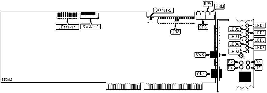
CONNECTIONS | |||
|
Function |
Label |
Function |
Label |
|
RJ-45 UTP connector |
CN1 |
MVIP connector |
CN2 |
|
USER CONFIGURABLE SETTINGS | ||
|
Function |
Label |
Position |
|
Card is first and only card in system |
SW3/1 |
On |
|
Card is not first in a multiple card system |
SW3/1 |
Off |
|
T1 loopback test disabled |
SW5 |
Off |
|
T1 loopback test enabled |
SW5 |
On |
|
BASE I/O ADDRESS SELECTION | |||||||
|
Setting |
SW3/2 |
SW3/3 |
SW3/4 |
SW3/5 |
SW3/6 |
SW3/7 |
SW3/8 |
|
100h |
On |
On |
On |
On |
On |
Off |
On |
|
108h |
On |
On |
On |
Off |
On |
Off |
On |
|
110h |
On |
On |
On |
On |
Off |
Off |
On |
|
118h |
On |
On |
On |
On |
On |
On |
Off |
|
120h |
On |
On |
Off |
On |
On |
On |
Off |
|
260h |
On |
On |
Off |
Off |
On |
On |
Off |
|
3D8h |
Off |
Off |
Off |
Off |
On |
On |
Off |
|
3E0h |
Off |
Off |
Off |
Off |
Off |
On |
On |
|
3E8h |
Off |
Off |
Off |
Off |
Off |
On |
Off |
|
3F0h |
Off |
Off |
Off |
Off |
Off |
Off |
On |
|
3F8h |
Off |
Off |
Off |
Off |
Off |
Off |
Off |
|
Note: A total of 255 base address settings are available. The switches are a binary representation of the decimal memory addresses. SW1/8 is the Most Significant Bit and switch SW1/1 is the Least Significant Bit. The switches have the following decimal values: SW1/8=32768, SW1/7=16384, SW1/6=8192, SW1/5=4096, SW1/4=2048, SW1/3=1024, SW1/2=512, SW1/1=256. Turn off the switches and add the values of the switches to obtain the correct memory address. (Off=1, On=0) | |||||||
|
INTERRUPT SELECTION | |
|
IRQ |
JP1 |
|
3 |
Pins 1 & 2 closed |
|
4 |
Pins 3 & 4 closed |
|
5 |
Pins 5 & 6 closed |
|
6 |
Pins 7 & 8 closed |
|
7 |
Pins 9 & 10 closed |
|
9 |
Pins 11 & 12 closed |
|
10 |
Pins 13 & 14 closed |
|
11 |
Pins 15 & 16 closed |
|
12 |
Pins 17 & 18 closed |
|
14 |
Pins 19 & 20 closed |
|
15 |
Pins 21 & 22 closed |
|
DIAGNOSTIC LED(S) | |||
|
LED |
Color |
Status |
Condition |
|
LED1 |
Red |
Blinking |
Data is being transmitted on channel 0 |
|
LED1 |
Red |
Blinking (fast) |
Channel 0 is off hook |
|
LED2 |
Red |
Blinking |
Data is being transmitted on channel 1 |
|
LED2 |
Red |
Blinking (fast) |
Channel 1 is off hook |
|
LED3 |
Red |
Blinking |
Data is being transmitted on channel 2 |
|
LED3 |
Red |
Blinking (fast) |
Channel 2 is off hook |
|
LED4 |
Red |
Blinking |
Data is being transmitted on channel 3 |
|
LED4 |
Red |
Blinking (fast) |
Channel 3 is off hook |
|
LED5 |
Red |
Blinking |
Data is being transmitted on channel 4 |
|
LED5 |
Red |
Blinking (fast) |
Channel 4 is off hook |
|
LED6 |
Red |
Blinking |
Data is being transmitted on channel 5 |
|
LED6 |
Red |
Blinking (fast) |
Channel 5 is off hook |
|
LED7 |
Red |
Blinking |
Data is being transmitted on channel 6 |
|
LED7 |
Red |
Blinking (fast) |
Channel 6 is off hook |
|
LED8 |
Red |
Blinking |
Data is being transmitted on channel 7 |
|
LED8 |
Red |
Blinking (fast) |
Channel 7 is off hook |
|
D1 |
Red |
On |
TR114+I8V-T1 in network loopback mode |
|
D2 |
Red |
On |
Loss of T1 network signal |
|
D3 |
Yellow |
On |
Failing to synchronize on incoming T1 signal |
|
D2 & D3 |
Red/Yellow |
Both on |
Board cannot detect a valid T1 signal |
|
D4 |
Green |
On |
Operating in normal mode |
|
FRM |
Unidentified |
On |
T1 framing error detected |
|
BPV |
Unidentified |
On |
T1 bipolar violation detected |
|
CRC |
Unidentified |
On |
Discrepancy in cyclic redundancy check detected |
|
MVIP CLOCK TERMINATION | ||
|
Setting |
SW4/1 |
SW4/2 |
|
Terminated |
On |
On |
|
Not terminated |
Off |
Off |
|
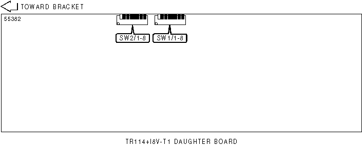
USER CONFIGURABLE SETTINGS | ||
|
Function |
Label |
Position |
|
T1 generates and transmits the clocking signals to the TR114 |
SW1/1 |
Off |
|
TR114 generates and transmits the clocking signals to T1 |
SW1/1 |
On |
|
Super frame mode |
SW1/2 |
Off |
|
Extended super frame mode |
SW1/2 |
On |
|
B8ZS line coding |
SW1/3 |
Off |
|
AMI line coding |
SW1/3 |
On |
|
MVIP clock master set to master |
SW2/3 |
Off |
|
MVIP clock master set to slave |
SW2/3 |
On |
|
T1 CABLE LENGTH SETTTINGS | |||
|
Cable Length |
SW1/4 |
SW1/5 |
SW1/6 |
|
0 to 132 ft. |
On |
On |
On |
|
133 to 266 ft. |
Off |
On |
On |
|
267 to 398 ft. |
On |
Off |
On |
|
399 to 532 ft. |
Off |
Off |
On |
|
533 to 654 ft. |
On |
On |
Off |
|
MVIP STREAM SELECT | ||
|
Mode |
SW2/1 |
SW2/2 |
|
6/7 |
Off |
Off |
|
4/5 |
On |
Off |
|
2/3 |
Off |
On |
|
0/1 |
On |
On |
|
SYNC SOURCE CONTROL | ||
|
Setting |
SW2/3 |
SW2/4 |
|
TR114+I8V-T1 controls |
Off |
Off |
|
Secondary net card controls |
Off |
On |
|
FRAMING SIGNAL OUTPUT | ||
|
Setting |
SW2/3 |
SW2/4 |
|
Disable output |
On |
Off |
|
Enable output |
On |
On |
|
TERMINATION | ||
|
Setting |
SW2/5 |
SW2/6 |
|
Unterminated |
Off |
Off |
|
Terminated |
On |
On |