MOTOROLA, INC.
6520/6560 MPROUTER DSPM/E&M CARD
|
Card Type |
Telephony |
|
Chip Set |
Unidentified |
|
I/O Options |
Telephone in/out (2), MVIP bus |
|
Data Bus |
16-bit ISA |
|
Line Type |
E & M |
|
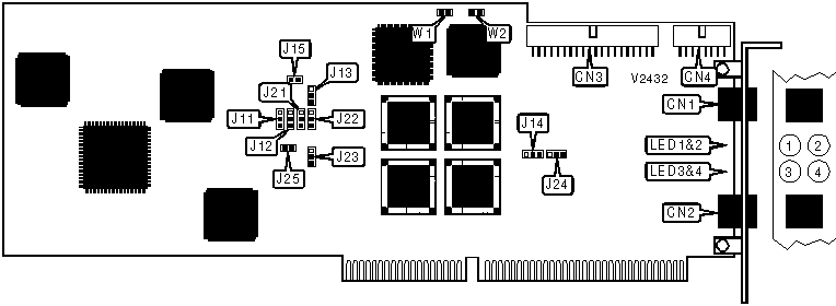
CONNECTIONS | |||
|
Function |
Label |
Function |
Label |
|
Line 1 |
CN1 |
MVIP bus (not used) |
CN3 |
|
Line 2 |
CN2 |
48V DC power in |
CN4 |
|
USER CONFIGURABLE SETTINGS | |||
|
Setting |
Label |
Position | |
| » |
Line 1 complex impedance type set for German operation |
J13 |
Pins 1 & 2 closed |
|
Line 1 complex impedance type set for UK operation |
J13 |
Pins 2 & 3 closed | |
| » |
Line 2 complex impedance type set for German operation |
J23 |
Pins 1 & 2 closed |
|
Line 2 complex impedance type set for UK operation |
J23 |
Pins 2 & 3 closed | |
|
MVIP BUS TERMINATION (NOT USED) | |||
|
Setting |
W1 |
W2 | |
| » |
Not terminated |
Open |
Open |
|
Terminated |
Closed |
Closed | |
|
LINE 1 IMPEDANCE TYPE | |||
|
Setting |
J11 |
J14 | |
| » |
Simple 600 ohm impedance |
Pins 1 & 2 closed |
Pins 2 & 3 closed |
|
Complex impedance |
Pins 2 & 3 closed |
Pins 1 & 2 closed | |
|
LINE 2 IMPEDANCE TYPE | |||
|
Setting |
J21 |
J24 | |
| » |
Simple 600 ohm impedance |
Pins 1 & 2 closed |
Pins 2 & 3 closed |
|
Complex impedance |
Pins 2 & 3 closed |
Pins 1 & 2 closed | |
|
LINE 1 TYPE | |||
|
Setting |
J12 |
J15 | |
| » |
Four-wire |
Pins 1 & 2 closed |
Open |
|
Two-wire |
Pins 2 & 3 closed |
Closed | |
|
LINE 2 TYPE | |||
|
Setting |
J22 |
J25 | |
| » |
Four-wire |
Pins 1 & 2 closed |
Open |
|
Two-wire |
Pins 2 & 3 closed |
Closed | |
|
DIAGNOSTIC LED(S) | |||
|
LED |
Color |
Status |
Condition |
|
LED1 |
Green |
On |
Line 1 local connection is off hook |
|
LED1 |
Green |
Off |
Line 1 local connection is on hook |
|
LED2 |
Green |
On |
Line 1 remote connection is off hook |
|
LED2 |
Green |
Off |
Line 1 remote connection is on hook |
|
LED3 |
Green |
On |
Line 2 local connection is off hook |
|
LED3 |
Green |
Off |
Line 2 local connection is on hook |
|
LED4 |
Green |
On |
Line 2 remote connection is off hook |
|
LED4 |
Green |
Off |
Line 2 remote connection is on hook |
|
MISCELLANEOUS TECHNICAL NOTE |
|
This card is designed for use in Motorola’s 6520/6560 MPRouter system and will not function in another system. See documents M3596 and M3597 for more information. |
|
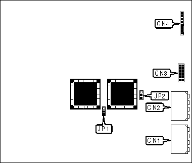
CONNECTIONS | |||
|
Function |
Label |
Function |
Label |
|
Connector to computer power supply |
CN1 |
Status connector |
CN3 |
|
Connector to computer power supply |
CN2 |
48V DC power out |
CN4 |
|
USER CONFIGURABLE SETTINGS | |||
|
Setting |
Label |
Position | |
| » |
Ring generation enabled |
JP1 |
Pins 2 & 3 closed |
|
Ring generation disabled |
JP1 |
Pins 1 & 2 closed | |
| » |
Ring frequency set to 25Hz |
JP2 |
Pins 2 & 3 closed |
|
Ring frequency set to 50Hz |
JP2 |
Pins 1 & 2 closed | |
|
MISCELLANEOUS TECHNICAL NOTE |
|
This power supply can power up to six DSPM/E&M cards via an included multi-connector cable. |