MULTI-TECH SYSTEMS, INC.
ISI3334/4, ISI3334/8, ISI3334/EC
|
Card Type |
Modem (asynchronous) |
|
Processor Type |
80186 |
|
Processor Speed |
16MHz |
|
Chip Set |
Unidentified |
|
Maximum Onboard Memory |
256KB RAM |
|
Maximum Data Rate |
33.6Kbps x 4 (8 with daughtercard) |
|
Maximum Fax Rate |
14.4Kbps x 4 (8 with daughtercard) |
|
Data Bus |
16-bit ISA |
|
Fax Class |
Class II |
|
Data Modulation Protocol |
Bell 103A/212A ITU-T V.22, V.22bis, V.32, V.32bis, V.34 AT&T V.32terbo |
|
Fax Modulation Protocol |
ITU-T V.17, V.21CH2, V.27ter, V.29 |
|
Error Correction/Compression |
MNP5, V.42, V.42bis |
|
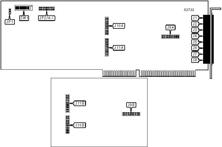
CONNECTIONS | |||
|
Function |
Label |
Function |
Label |
|
Telephone line 1 out |
J1 |
Telephone line 8 out |
J8 |
|
Telephone line 2 out |
J2 |
Header to daughterboard J9B |
J9A |
|
Telephone line 3 out |
J3 |
Header to main board J9A |
J9B |
|
Telephone line 4 out |
J4 |
Header to daughterboard J10B |
J10A |
|
Telephone line 5 out |
J5 |
Header to main board J10A |
J10B |
|
Telephone line 6 out |
J6 |
Header to daughterboard J11B |
J11A |
|
Telephone line 7 out |
J7 |
Header to main board J11A |
J11B |
Note: J5 through J8 will not be active unless the daughtercard is installed. | |||
|
USER CONFIGURABLE SETTINGS | ||
|
Setting |
Label |
Position |
|
í Daughtercard is not installed |
JP1 |
Pins 1 & 2 closed |
|
Daughtercard is installed |
JP1 |
Pins 2 & 3 closed |
|
INTERRUPT SELECTION | |||||||||
|
Setting |
JP2/A |
JP2/B |
JP2/C |
JP2/D |
JP2/E |
JP2/F |
JP2/G |
JP2/H |
JP2/I |
|
2 |
Closed |
Open |
Open |
Open |
Open |
Open |
Open |
Open |
Open |
|
í 3 |
Open |
Closed |
Open |
Open |
Open |
Open |
Open |
Open |
Open |
|
4 |
Open |
Open |
Closed |
Open |
Open |
Open |
Open |
Open |
Open |
|
5 |
Open |
Open |
Open |
Closed |
Open |
Open |
Open |
Open |
Open |
|
7 |
Open |
Open |
Open |
Open |
Closed |
Open |
Open |
Open |
Open |
|
10 |
Open |
Open |
Open |
Open |
Open |
Closed |
Open |
Open |
Open |
|
11 |
Open |
Open |
Open |
Open |
Open |
Open |
Closed |
Open |
Open |
|
12 |
Open |
Open |
Open |
Open |
Open |
Open |
Open |
Closed |
Open |
|
15 |
Open |
Open |
Open |
Open |
Open |
Open |
Open |
Open |
Closed |
|
BASE I/O ADDRESS SELECTION | ||||||||
|
Setting |
SW1/1 |
SW1/2 |
SW1/3 |
SW1/4 |
SW1/5 |
SW1/6 |
SW1/7 |
SW1/8 |
|
000h |
On |
On |
On |
On |
On |
On |
On |
On |
|
008h |
Off |
On |
On |
On |
On |
On |
On |
On |
|
010h |
On |
Off |
On |
On |
On |
On |
On |
On |
|
018h |
Off |
Off |
On |
On |
On |
On |
On |
On |
|
020h |
On |
On |
Off |
On |
On |
On |
On |
On |
|
í 200h |
On |
On |
On |
On |
On |
On |
Off |
On |
|
7D8h |
Off |
Off |
On |
Off |
Off |
Off |
Off |
Off |
|
7E0h |
On |
On |
Off |
Off |
Off |
Off |
Off |
Off |
|
7E8h |
Off |
On |
Off |
Off |
Off |
Off |
Off |
Off |
|
7F0h |
On |
Off |
Off |
Off |
Off |
Off |
Off |
Off |
|
7F8h |
Off |
Off |
Off |
Off |
Off |
Off |
Off |
Off |
Note: A total of 256 base address settings are available. The switches are a binary representation of the decimal memory addresses. SW1/8 is the Most Significant Bit and switch SW1/1 is the Least Significant Bit. The switches have the following decimal values: SW1/8=1024, SW1/7=512, SW1/6=256, SW1/5=128, SW1/4=64, SW1/3=32, SW1/2=16, SW1/1=8. Turn off the switches and add the values of the switches that are off to obtain the correct memory address. (Off=1, On=0) | ||||||||
|
SUPPORTED STANDARD COMMANDS |
|
Basic AT Commands |
|
+++, ‘comma’, A/ |
|
A, B, D, E, H, O, P, T, V, W, X, Y, Z |
|
&D, &F, &G, &P, &S, &T, &W |
|
S-Registers |
|
S0, S1, S2, S3, S4, S5, S6, S7, S8, S9, S10, S11, S30 |
Note: See MHI documentation for complete information. |
Proprietary AT Command Set
|
ANSWER/ORIGINATE MODE | ||
|
Type: |
Configuration | |
|
Format: |
AT [cmds] Rn [cmds] | |
|
Description: |
Selects whether the modem will answer and originate calls in normal or reversed mode. | |
|
Command |
Function | |
|
í R0 |
Modem will answer calls in answer mode and originate calls in originate mode. | |
|
R1 |
Modem will answer calls in originate mode and originate calls in answer mode. | |
|
AUTO-RELIABLE FALLBACK | |
|
Type: |
Configuration |
|
Format: |
AT [cmds] $Fn [cmds] |
|
Description: |
Selects whether error correction can be disabled by a <CR> while handshaking. |
|
Command |
Function |
|
$F0 |
Auto-reliable fallback disabled. |
|
í $F1 |
Auto-reliable fallback enabled. |
|
AUTO-RELIABLE TIME BUFFER CONFIGURATION | |
|
Type: |
Configuration |
|
Format: |
AT [cmds] $An [cmds] |
|
Description: |
Controls the handling of incoming data during auto-reliable time period. |
|
Command |
Function |
|
í $A0 |
Data is discarded. |
|
$A1 |
Data is buffered. |
|
BREAK LENGTH | |
|
Type: |
Configuration |
|
Format: |
AT [cmds] S17=n [cmds] |
|
Default: |
250 |
|
Range: |
0 - 250 |
|
Unit: |
10 mS |
|
Description: |
Sets the length of the break signal the modem will send to the local serial port. |
|
BUFFER SIZE | |
|
Type: |
Configuration |
|
Format: |
AT [cmds] &Bn [cmds] |
|
Description: |
Selects the modem’s transmit/receive buffer size. |
|
Command |
Function |
|
í &B0 |
Normal buffer size. |
|
&B1 |
Small buffer size. |
|
CD SIGNAL | |
|
Type: |
Configuration |
|
Format: |
AT [cmds] &Cn [cmds] |
|
Description: |
Configures the behavior of the carrier detect signal. |
|
Command |
Function |
|
&C0 |
CD forced high. |
|
í &C1 |
CD normal. |
|
&C2 |
CD forced high except during disconnect. |
|
&C4 |
Modem resets on low CD. |
|
CLEAR DOWN SIGNAL | ||
|
Type: |
Configuration | |
|
Format: |
AT [cmds] &CDn [cmds] | |
|
Description: |
Selects whether the modem will send a clear down signal when disconnecting. | |
|
Command |
Function | |
|
í &CD0 |
Modem will not send clear down signal. | |
|
&CD1 |
Modem will send clear down signal. | |
|
COMMAND SET | |
|
Type: |
Configuration |
|
Format: |
AT &Qn |
|
Description: |
Selects standard Hayes or custom command sets. |
|
Command |
Function |
|
í &Q0 |
Multi-Tech custom command set enabled. |
|
&Q1 |
Standard Hayes command set enabled. |
|
COMPRESSION | |
|
Type: |
Configuration |
|
Format: |
AT &En |
|
Description: |
Selects data compression. |
|
Command |
Function |
|
&E14 |
Data compression disabled. |
|
í &E15 |
Data compression enabled. |
|
COMPRESSION MODE | |
|
Type: |
Configuration |
|
Format: |
AT #Ln |
|
Description: |
Selects active compression protocols. |
|
Command |
Function |
|
í #L0 |
MNP and V.42 negotiation enabled. |
|
#L1 |
MNP negotiation enabled. |
|
#L2 |
V.42 negotiation enabled. |
|
#L3 |
V.42 enabled with no negotiation. |
|
CTS SIGNAL | |
|
Type: |
Configuration |
|
Format: |
AT [cmds] &Rn [cmds] |
|
Description: |
Controls the behaviour of the CTS signal. |
|
Command |
Function |
|
&R0 |
CTS normal. |
|
í &R1 |
CTS forced high in command mode. |
|
&R2 |
CTS forced low for 1 second during disconnect. |
|
CTS SIGNAL | |
|
Type: |
Configuration |
|
Format: |
AT [cmds] &RFn [cmds] |
|
Description: |
Selects the function of the CTS signal. |
|
Command |
Function |
|
&RF0 |
CTS follows RTS. |
|
í &RF1 |
CTS normal. |
|
DATA LENGTH | |
|
Type: |
Configuration |
|
Format: |
AT [cmds] $EBn [cmds] |
|
Description: |
Selects 10- or 11-bit mode. |
|
Command |
Function |
|
í $EB0 |
Sets 10-bit mode. |
|
$EB1 |
Sets 11-bit mode. |
|
DATA PARITY | |
|
Type: |
Configuration |
|
Format: |
AT [cmds] #Pn [cmds] |
|
Description: |
Sets the parity of the serial port. |
|
Command |
Function |
|
í #P0 |
No parity. |
|
#P1 |
Odd parity. |
|
#P2 |
Even parity. |
|
DATA PUMP TONE | ||
|
Type: |
Configuration | |
|
Format: |
AT [cmds] $FCn [cmds] | |
|
Description: |
Selects whether the data pump will transmit a 5 second 2100Hz tone. | |
|
Command |
Function | |
|
$FC0 |
Data pump will not transmit tone. | |
|
í $FC1 |
Data pump will transmit tone. | |
|
DIAL STORED PHONE NUMBER | |
|
Type: |
Immediate |
|
Format: |
AT [cmds] Na [Nb, Nc...] |
|
Description: |
Dials stored phone number(s). If the first number is busy, the modem will proceed to the next number in the list. |
|
DISCONNECT SIGNAL DROP - PBX | |
|
Type: |
Register |
|
Format: |
AT [cmds] S24=n [cmds] |
|
Default: |
20 |
|
Range: |
0 - 255 |
|
Unit: |
50 ms |
|
Description: |
Sets the time to drop the DTR, CTS, and DCD signals on disconnect when modem is connected to a PBX. |
|
DISPLAY CONFIGURATION | |
|
Type: |
Immediate |
|
Format: |
AT Ln |
|
Description: |
Displays modem configuration. |
|
Command |
Function |
|
L5 |
Displays all settings. |
|
L6 |
Displays the values of all S-registers. |
|
L7 |
Displays extended parameters. |
|
L8 |
Displays current diagnostics. |
|
L9 |
Displays current signal strength. |
|
L10 |
Displays current signal-to-noise ratio. |
|
L11 |
Displays current noise level. |
|
DISPLAY INFORMATION | |
|
Type: |
Immediate |
|
Format: |
AT [cmds] In [cmds] |
|
Description: |
Displays information requested about the modem. |
|
Command |
Function |
|
I0 |
Displays product identification code. |
|
I1 |
Displays firmware revision. |
|
I2 |
Displays product name. |
|
I3 |
Factory use only. |
|
I5 |
Displays DSP chip version. |
|
I9 |
Displays modem features. |
|
DSR SIGNAL | |
|
Type: |
Configuration |
|
Format: |
AT [cmds] &SFn [cmds] |
|
Description: |
Selects the function of the DSR signal. |
|
Command |
Function |
|
í &SF0 |
DSR is set to CD. |
|
&SF1 |
DSR is independent of CD. |
|
DTR DIALING | |
|
Type: |
Configuration |
|
Format: |
AT [cmds] $Dn [cmds] |
|
Description: |
Selects the DTR dialing function. |
|
Command |
Function |
|
í $D0 |
DTR dialing disabled. |
|
$D1 |
DTR dialing enabled. |
|
DTR SIGNAL DROP | |
|
Type: |
Register |
|
Format: |
AT [cmds] S25=n [cmds] |
|
Default: |
0 |
|
Range: |
0 - 255 |
|
Unit: |
100 ms |
|
Description: |
Sets the time to drop the DTR signal on disconnect. A value of 0 sets this to 50 mS. |
|
ESCAPE SEQUENCE BUFFER SIZE | |
|
Type: |
Register |
|
Format: |
AT [cmds] S34=n [cmds] |
|
Default: |
10 |
|
Range: |
0-60 |
|
Unit: |
1 byte |
|
Description: |
Sets the size of the buffer used to store entered commands during an escape sequence. |
|
ESCAPE SEQUENCE RESPONSE | |
|
Type: |
Configuration |
|
Format: |
AT [cmds] %En [cmds] |
|
Description: |
Sets the response that the modem will give to an escape sequence. |
|
%E4 |
OK response to command escape disabled. |
|
í %E5 |
OK response to command escape enabled. |
|
ESCAPE SEQUENCE TIMEOUT | |
|
Type: |
Register |
|
Format: |
AT [cmds] S32=n [cmds] |
|
Default: |
20 |
|
Range: |
0-255 |
|
Unit: |
1 second |
|
Description: |
Sets the maximum amount of time the modem will wait for a <CR> while executing an escape sequence. |
|
ESCAPE SEQUENCE TYPE | |
|
Type: |
Configuration |
|
Format: |
AT [cmds] %En [cmds] |
|
Description: |
Sets the type of command escape sequence the modem will recognise. |
|
Command |
Function |
|
%E0 |
Command escape disabled. |
|
í %E1 |
TIES escape (+++AT...) |
|
%E2 |
<BREAK> AT method. |
|
%E3 |
Both TIES and BREAK methods. |
|
FALLBACK MODE | |
|
Type: |
Configuration |
|
Format: |
AT [cmds] #Fn [cmds] |
|
Description: |
Sets direction of fallback. |
|
Command |
Function |
|
#F0 |
Fallback disabled. |
|
#F1 |
Fallback from 33.6Kbps to 2400bps as line quality degrades. |
|
í #F2 |
Fallback from 2400bps to 33.6Kbps as line quality improves. |
|
FLOW CONTROL | |
|
Type: |
Configuration |
|
Format: |
AT [cmds] &En [cmds] |
|
Description: |
Selects flow control. |
|
Command |
Function |
|
&E12 |
Flow control disabled. |
|
í &E13 |
Flow control enabled. |
|
FLOW CONTROL - ENQ/ACK | |
|
Type: |
Configuration |
|
Format: |
AT [cmds] &En [cmds] |
|
Description: |
Selects ENQ/ACK pacing. |
|
Command |
Function |
|
í &E8 |
Enables ENQ/ACK pacing. |
|
&E9 |
Disables ENQ/ACK pacing. |
|
FLOW CONTROL IN NORMAL MODE | |
|
Type: |
Configuration |
|
Format: |
AT [cmds] &En [cmds] |
|
Description: |
Selects XON/XOFF flow control for non-error-correcting connections. |
|
Command |
Function |
|
í &E10 |
XON/XOFF disabled for non-error-correcting connections. |
|
&E11 |
XON/XOFF enabled for non-error-correcting connections. |
|
FLOW CONTROL TYPE | |
|
Type: |
Configuration |
|
Format: |
AT [cmds] &En [cmds] |
|
Description: |
Sets type of flow control used by modem. |
|
Command |
Function |
|
&E3 |
Flow control disabled. |
|
í &E4 |
CTS/RTS flow control enabled. |
|
&E5 |
XON/XOFF flow control enabled. |
|
HANDSHAKE ATTEMPTS | |
|
Type: |
Configuration |
|
Format: |
AT [cmds] #An [cmds] |
|
Description: |
Configures the initial handshake phase. |
|
Command |
Function |
|
í #A0 |
Attempts speeds in order: 33.6Kbps, 31.2Kbps, 28.8Kbps, 24Kbps, 21.6Kbps, 19.2Kbps, 16.8Kbps, 14.4Kbps, 12Kbps, 9600bps, 4800bps, 2400bps, 1200bps, 300bps. |
|
#A1 |
Attempts only 33.6Kbps. |
|
#A2 |
Attempts speeds in order: 33.6Kbps, 31.2Kbps, 28.8Kbps, 24Kbps, 21.6Kbps, 19.2Kbps, 16.8Kbps, 14.4Kbps, 12Kbps, 9600bps, 4800bps. |
|
#A3 |
Attempts speeds in order: 2400bps, 1200bps, 300bps. |
|
HELP SCREENS | |
|
Type: |
Immediate |
|
Format: |
AT $Hn |
|
Description: |
Shows modem help screens. |
|
Command |
Function |
|
$H1 |
Shows help screen 1. |
|
$H2 |
Shows help screen 2. |
|
$H3 |
Shows help screen 3. |
|
LOCAL SERIAL PORT SPEED | |
|
Type: |
Configuration |
|
Format: |
AT [cmds] $SBnnn [cmds] |
|
Description: |
Sets serial port speed. |
|
Command |
Function |
|
$SB300 |
Sets 300bps speed. |
|
$SB1200 |
Sets 1200bps speed. |
|
$SB2400 |
Sets 2400bps speed. |
|
$SB4800 |
Sets 4800bps speed. |
|
$SB9600 |
Sets 9600bps speed. |
|
$SB19200 |
Sets 19.2Kbps speed. |
|
$SB38400 |
Sets 38.4Kbps speed. |
|
$SB57600 |
Sets 57.6Kbps speed. |
|
í $SB115200 |
Sets 115.2Kbps speed. |
|
LOCK SERIAL PORT | |
|
Type: |
Configuration |
|
Format: |
AT [cmds] $BAn [cmds] |
|
Description: |
Sets operation of serial port speed. |
|
Command |
Function |
|
í $BA0 |
Serial speed locked at rate set by $SB. |
|
$BA1 |
Serial speed follows connect speed, ignoring $SB. |
|
LOGIN PASSWORD | |
|
Type: |
Configuration |
|
Format: |
AT [cmds] #Ixxxx |
|
Description: |
Sets the login password to xxxx. The password must be between 6 and 10 characters, case sensitive. It defaults to MULTI-TECH. |
|
MAXIMUM BLOCK SIZE FOR TRANSMISSION | |
|
Type: |
Configuration |
|
Format: |
AT [cmds] &BSn [cmds] |
|
Description: |
Sets the maximum transmittable block size for data compression modes. |
|
Command |
Function |
|
&BS0 |
Maximum block size is 64 characters. |
|
í &BS1 |
Maximum block size is 256 characters in MNP mode and 128 characters in LAPM mode. |
|
MAXIMUM LINE SPEED | |
|
Type: |
Configuration |
|
Format: |
AT $MBnnn |
|
Description: |
Sets the maximum allowable data exchange rate attempted during handshake process. |
|
Command |
Function |
|
$MB75 |
Sets V.23 (1200bps/75bps bi-directional). |
|
$MB300 |
Sets 300bps maximum connect speed. |
|
$MB1200 |
Sets 1200bps maximum connect speed. |
|
$MB2400 |
Sets 2400bps maximum connect speed. |
|
$MB4800 |
Sets 4800bps maximum connect speed. |
|
$MB9600 |
Sets 9600bps maximum connect speed. |
|
$MB14400 |
Sets 14.4Kbps maximum connect speed. |
|
$MB19200 |
Sets 19.2Kbps maximum connect speed. |
|
$MB28800 |
Sets 28.8Kbps maximum connect speed. |
|
í $MB33600 |
Sets 33.6Kbps maximum connect speed. |
|
REDIAL | |
|
Type: |
Immediate |
|
Format: |
A: |
|
Description: |
Redials the last number dialed until it is no longer busy. |
|
Note: |
Do not precede this command with AT or follow it with <CR>. |
|
REMOTE CONFIGURATION CHARACTER | |
|
Type: |
Register |
|
Format: |
AT [cmds] S13=n [cmds] |
|
Default: |
37 |
|
Range: |
0 - 127 |
|
Unit: |
1 ASCII character |
|
Description: |
Defines the character that, when sent four times within the guard time set by S12, will notify the remote modem that a remote configuration session has been requested. |
|
RESULT CODES | |
|
Type: |
Configuration |
|
Format: |
AT [cmds] Qn [cmds] |
|
Description: |
Enables modem to send result codes to the DTE. |
|
Command |
Function |
|
í Q0 |
Result codes enabled. |
|
Q1 |
Result codes disabled. |
|
Q2 |
Dumb answer mode enabled. |
|
RETRANSMIT FAIL ACTION | |
|
Type: |
Configuration |
|
Format: |
AT [cmds] $Rn [cmds] |
|
Description: |
Sets whether the modem gives up on a bad connection. |
|
Command |
Function |
|
í $R0 |
Hang up after 12 failed retransmissions. |
|
$R1 |
Do not hang up after 12 failed retransmissions. |
|
SETUP PASSWORD | |
|
Type: |
Configuration |
|
Format: |
AT [cmds] #Sxxxx |
|
Description: |
Sets the setup password to xxxx. The password must be between 6 and 10 characters, case sensitive. It defaults to MODEMSETUP. |
|
TEST MODES | |
|
Type: |
Immediate |
|
Format: |
AT [cmds] Un [cmds] |
|
Description: |
Performs test modes. |
|
Command |
Function |
|
U0 |
Begin local analog loopback test in originate mode. |
|
U1 |
Begin local analog loopback test in answer mode. |
|
U2 |
Request remote digital loopback |
|
U3 |
Begin local digital loopback. |
|
TIME UNTIL OFF HOOK ON HIGH DTR | |
|
Type: |
Register |
|
Format: |
AT [cmds] S37=n [cmds] |
|
Default: |
0 |
|
Range: |
0-255 |
|
Unit: |
1 second |
|
Description: |
Sets the amount of time the modem will wait to pick up after the DTR signal goes high. |
|
TIME UNTIL ON HOOK ON LOW DTR | |
|
Type: |
Register |
|
Format: |
AT [cmds] S36=n [cmds] |
|
Default: |
0 |
|
Range: |
0-255 |
|
Unit: |
1 second |
|
Description: |
Sets the amount of time the modem will wait to hang up after the DTR signal goes low. |
|
TRELLIS CODING | ||
|
Type: |
Configuration | |
|
Format: |
AT [cmds] #Tn [cmds] | |
|
Description: |
Selects whether the modem will use trellis coding. | |
|
Command |
Function | |
|
#T0 |
Trellis coding disabled. | |
|
í #T1 |
Trellis coding enabled. | |
|
V.32terbo CONTROL | |
|
Type: |
Configuration |
|
Format: |
AT [cmds] #Vn [cmds] |
|
Description: |
Controls the V.32terbo protocol in answer mode. |
|
Command |
Function |
|
í #V0 |
V.32terbo enabled. |
|
#V1 |
V.32terbo disabled. |
|
V.34 LINE PROBE | ||
|
Type: |
Configuration | |
|
Format: |
AT [cmds] %DPn [cmds] | |
|
Description: |
Selects whether the modem will read line probe information from the DSP chip during handshaking. | |
|
Command |
Function | |
|
í %DP0 |
Line probe information not read during handshaking. | |
|
%DP1 |
Line probe information read during handshaking. | |
|
V.34 LINE PROBE - DISPLAY | ||
|
Type: |
Immediate | |
|
Format: |
AT [cmds] %DFn [cmds] | |
|
Description: |
Displays V.34 line probe data. | |
|
Command |
Function | |
|
%DF0 |
Displays V.34 line probe data in graph format. | |
|
%DF1 |
Displays V.34 line probe data in table format. | |
|
V.34 - MAXIMUM LINE SPEED | ||
|
Type: |
Register | |
|
Format: |
AT [cmds] S48=n [cmds] | |
|
Description: |
Sets the maximum line speed the modem will attempt to connect at when in V.34 mode. | |
|
Command |
Function | |
|
í S48=0 |
Modem will attempt to connect at 33.6Kbps. | |
|
S48=4 |
Modem will attempt to connect at 4800bps. | |
|
S48=9 |
Modem will attempt to connect at 9600bps. | |
|
S48=12 |
Modem will attempt to connect at 12Kbps. | |
|
S48=14 |
Modem will attempt to connect at 14.4Kbps. | |
|
S48=16 |
Modem will attempt to connect at 16.8Kbps. | |
|
S48=19 |
Modem will attempt to connect at 19.2Kbps. | |
|
S48=21 |
Modem will attempt to connect at 21.6Kbps. | |
|
S48=26 |
Modem will attempt to connect at 26.4Kbps. | |
|
S48=28 |
Modem will attempt to connect at 28.8Kbps. | |
|
S48=31 |
Modem will attempt to connect at 31.2Kbps. | |
|
S48=33 |
Modem will attempt to connect at 33.6Kbps. | |
|
V.42 FAILURE REACTION | |
|
Type: |
Configuration |
|
Format: |
AT [cmds] &En [cmds] |
|
Description: |
Sets the modem's reaction if it fails to connect with V.42. |
|
Command |
Function |
|
&E0 |
Error correction disabled. |
|
í &E1 |
Modem will fall back to normal mode. |
|
&E2 |
Modem will not fall back to normal mode. |
|
XOFF SEND | |
|
Type: |
Configuration |
|
Format: |
AT [cmds] #Xn [cmds] |
|
Description: |
Selects how XOFF signal is sent. |
|
Command |
Function |
|
í #X0 |
Single XOFF character are sent until the DTE responds. |
|
#X1 |
Multiple XOFF characters are sent until the DTE responds. |
|
XON/XOFF PASS-THROUGH | |
|
Type: |
Configuration |
|
Format: |
AT [cmds] &En [cmds] |
|
Description: |
Selects whether XON/XOFF signals are sent to remote modem. |
|
Command |
Function |
|
í &E6 |
XON/XOFF signals trapped by local modem. |
|
&E7 |
XON/XOFF passed through local modem. |