VEN-TEL, INC.
VT24V42FAX
|
Modem Type |
Data (synchronous/asynchronous)/Fax |
|
Maximum Data Rate |
2400bps |
|
Maximum Fax Rate |
9600bps |
|
Data Bus |
External |
|
Fax Class |
Class I & II |
|
Data Modulation Protocol |
Bell 103A/212A ITU-T V.21, V.22, V.22bis, V.23 |
|
Fax Modulation Protocol |
Unidentified |
|
Error Correction/Compression |
MNP5, MNP10, V.42, V.42bis |
|
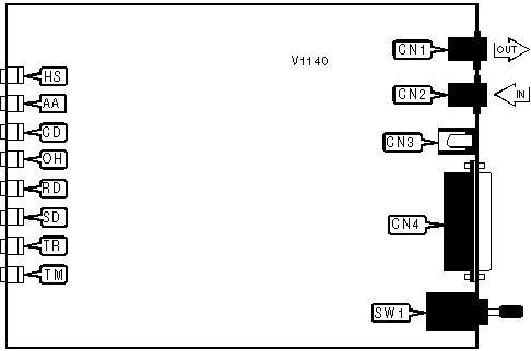
CONNECTIONS | |||
|
Purpose |
Location |
Purpose |
Location |
|
Line out |
CN1 |
RS-232/422 |
CN4 |
|
Line in |
CN2 |
Power switch |
SW1 |
|
DC power |
CN3 | ||
|
DIAGNOSTIC LED(S) | |||
|
LED |
Color |
Status |
Condition |
|
HS |
Red |
On |
Modem is operating at 2400bps |
|
HS |
Red |
Off |
Modem is operating at less than 2400bps |
|
AA |
Red |
On |
Auto answer enabled |
|
AA |
Red |
Off |
Auto answer disabled |
|
CD |
Red |
On |
Carrier signal detected |
|
CD |
Red |
Off |
Carrier signal not detected |
|
OH |
Red |
On |
Modem is off-hook |
|
OH |
Red |
Off |
Modem is on-hook |
|
RD |
Red |
On |
Modem is receiving data |
|
RD |
Red |
Off |
Modem is not receiving data |
|
SD |
Red |
On |
Modem is transmitting data |
|
SD |
Red |
Off |
Modem is not transmitting data |
|
TR |
Red |
On |
DTR signal is high |
|
TR |
Red |
Off |
DTR signal is low |
|
TM |
Red |
Blinking |
Test mode enabled |
|
TM |
Red |
Off |
Test mode disabled |
Proprietary Command Set
|
BIT-MAPPED REGISTER S14 | |||
|
Format |
AT [cmds] S14=n [cmds] | ||
|
Example: |
ATS14=139 <CR> | ||
|
Default: |
171 | ||
|
Range: |
0 - 255 | ||
|
Unit: |
Bit-mapped | ||
|
Description: |
Controls echo, quiet mode, result codes, dial mode, and originate/answer mode. | ||
|
Bit | Value |
Function | |
|
0 | 1 |
Not used. | |
|
1 | 0 » 1 |
Command echo function disabled. Command echo function enabled. | |
|
2 | » 0 1 |
Result code sending disabled. Result code sending enabled. | |
|
3 | 0 » 1 |
Numeric format enabled. Verbose format enabled. | |
|
4 | 0 |
Not used. | |
|
5 | 0 » 1 |
Tone dialing mode enabled. Pulse dialing mode enabled. | |
|
6 | » 0 1 |
Result codes normal. Result codes disabled in answer mode. | |
|
7 | 0 » 1 |
Answer mode enabled. Originate mode enabled. | |
|
BIT-MAPPED REGISTER S21 | |||
|
Format |
AT [cmds] S21=n [cmds] | ||
|
Example: |
ATS21=1 <CR> | ||
|
Default: |
0 | ||
|
Range: |
0 - 255 | ||
|
Unit: |
Bit-mapped | ||
|
Description: |
Controls low DTR action, DCD signal, and the Long Space Disconnect function. | ||
|
Bit | Value |
Function | |
|
0 | 0 |
Not used. | |
|
1 | » 0 1 |
Restore profile 0 on power-up. Restore profile 1 on power-up. | |
|
2 | 0 |
Not used. | |
|
4, 3 | » 00 01 10 11 |
DTR signal ignored. Modem goes to command mode on low DTR. Modem disconnects on low DTR. Auto-Answer is disabled. Modem is initialized on low DTR. | |
|
5 | » 0 1 |
DCD signal forced high. DCD signal normal. | |
|
6 | » 0 1 |
DSR signal forced high. DSR signal normal. | |
|
7 | » 0 1 |
Long Space Disconnect function disabled. Long Space Disconnect function enabled. | |
|
BIT-MAPPED REGISTER S22 | |||
|
Format |
AT [cmds] S22=n [cmds] | ||
|
Example: |
ATS22=114 <CR> | ||
|
Default: |
118 | ||
|
Range: |
0 - 255 | ||
|
Unit: |
Bit-mapped | ||
|
Description: |
Controls volume and speaker settings, result codes, and make/break pulse ratio. | ||
|
Bit | Value |
Function | |
|
1, 0 | 00 01 » 10 11 |
Lowest volume setting. Low volume setting. Medium volume setting Highest volume setting. | |
|
3, 2 | 00 » 01 10 11 |
Speaker disabled. Speaker enabled until carrier signal detected Speaker enabled. Speaker enabled following dialing, then disabled after carrier signal detected. | |
|
6, 5 ,4 | 000 100 101 110 » 111 |
Busy and dialtone detection disabled, result codes 0-4 enabled. Busy and dialtone detection disabled, result codes 0-5, 10 enabled. Busy tone detection disabled, dialtone detection enabled, result codes 0-6, 10 enabled. Busy tone detection enabled, dialtone detection disabled, result codes 0-5, 7, 10 enabled. Busy and dialtone detection enabled, result codes 0-7, 10 enabled. | |
|
7 | » 0 1 |
39/61ms pulse ratio at 10pps (North America) 33/67ms pulse ratio at 10pps (Europe) | |
|
BIT-MAPPED REGISTER S23 | |||
|
Format |
AT [cmds] S23=n [cmds] | ||
|
Example: |
ATS23=114 <CR> | ||
|
Default: |
0, read-only (see note) | ||
|
Range: |
0 - 255 | ||
|
Unit: |
Bit-mapped | ||
|
Description: |
Controls guard tones. Also indicates detected serial port speed and parity. Also provides storage for remote digital loopback tests. | ||
|
Note: |
All bits except bits 6 and 7 are read-only. | ||
|
Bit | Value |
Function | |
|
0 |
0 1 |
Remote digital loopback response disabled. Remote digital loopback response enabled. | |
|
3, 2, 1 | 000 001 010 011 100 » 101 |
Local speed detected at 300bps. Local speed detected at 600bps. Local speed detected at 1200bps. Local speed detected at 2400bps. Local speed detected at 4800bps. Local speed detected at 9600bps. | |
|
5, 4 |
00 01 11 |
Even parity detected. Odd parity detected. No parity detected. | |
|
7, 6 | » 00 01 10 |
Guard tone disabled. 550Hz guard tone enabled. 1800Hz guard tone enabled. | |
|
BIT-MAPPED REGISTER S27 | |||
|
Format |
AT [cmds] S27=n [cmds] | ||
|
Example: |
ATS27=77 <CR> | ||
|
Default: |
73 | ||
|
Range: |
0 - 255 | ||
|
Unit: |
Bit-mapped | ||
|
Description: |
Controls communications mode, line type, and protocol type. | ||
|
Note: |
Be aware that bits 2 and 3 are out of order. | ||
|
Bit | Value |
Function | |
|
3, 1, 0 |
000 001 010 011 100 101 110 |
Asynchronous mode, serial port speed follows connect speed. Asynchronous command mode and synchronous connect mode. Asynchronous command mode - modem autodials first number in directory on high DTR, then synchronous connect mode. Asynchronous command mode on low DTR, synchronous connect mode on high DTR. Hayes AutoSync™ mode - serial port locked at 9600bps. Error-correcting mode. Asynchronous mode, serial port speed locked. | |
|
2 | » 0 1 |
Select dial-up line. Select leased line. | |
|
5, 4 |
00 01 10 |
Modem generates clock Modem generates clock from the receive carrier signal. DTE generates clock | |
|
6 | » 0 1 |
Select CCITT protocols. Select Bell protocols. | |
|
7 | 0 |
Not used. | |
|
COMPRESSION | |
|
Type: |
Register |
|
Format: |
AT [cmds] S41=n [cmds] |
|
Example: |
AT S41=1 <CR> |
|
Description: |
Selects data compression. |
| Command |
Function |
| S41=0 |
Data compression disabled. |
| » S41=1 |
Data compression enabled. |
|
COMPRESSION MODE | |
|
Type: |
Configuration |
|
Format: |
AT #Ln |
|
Example: |
AT #L2 -K1 <CR> |
|
Description: |
Selects active compression protocols. |
| Command |
Function |
| #L0 |
Compression disabled. |
| #L1 |
MNP compression only enabled. |
| #L2 |
V.42bis compression only enabled. |
| » #L3 |
MNP and V.42bis compression enabled. |
|
FLOW CONTROL | |
|
Type: |
Configuration |
|
Format: |
AT [cmds] \Gn [cmds] |
|
Example: |
AT \G1 &K3 <CR> |
|
Description: |
Selects flow control. |
| Command |
Function |
| » \G0 |
Flow control disabled. |
| \G1 |
Flow control enabled. |
|
INACTIVITY TIMER | |
|
Type: |
Configuration |
|
Format: |
AT [cmds] \Tn [cmds] |
|
Example: |
AT\T20 <CR> |
|
Default: |
0 |
|
Range: |
0-42 |
|
Unit: |
1 minute |
|
Description: |
Sets the length of time that the modem does not receive information before it disconnects. |
|
LOOPBACK TESTS | |||
|
Format |
AT [cmds] S16=n [cmds] | ||
|
Example: |
ATS16=32 <CR> | ||
|
Default: |
0 | ||
|
Range: |
0 - 255 | ||
|
Unit: |
Bit-mapped | ||
|
Description: |
Enables loopback tests. | ||
|
Note: |
Bit 3 is read-only. | ||
|
Bit | Value |
Function | |
|
0 | » 0 1 |
Local analog loopback test disabled. Local analog loopback test enabled. | |
|
1 | 0 |
Not used. | |
|
2 | » 0 1 |
Local digital loopback test disabled. Local digital loopback test enabled. | |
|
3 | » 0 1 |
Modem is not performing remote digital loopback test. Modem is performing remote digital loopback test. | |
|
4 | » 0 1 |
Remote digital loopback test disabled. Remote digital loopback test enabled. | |
|
5 | » 0 1 |
Remote digital loopback with local self-test disabled. Remote digital loopback with local self-test enabled. | |
|
6 | » 0 1 |
Local analog loopback with local self-test disabled. Local analog loopback with local self-test enabled. | |
|
7 | 0 |
Not used. | |
|
MNP10 COMPRESSION | |
|
Type: |
Configuration |
|
Format: |
AT [cmds] -Kn [cmds] |
|
Example: |
AT %C1 -K1 -Q0 <CR> |
|
Description: |
Selects MNP10 data compression. |
| Command |
Function |
| -K0 |
MNP10 disabled. |
| » -K1 |
MNP10 enabled. |