VEN-TEL, INC.
EC96
|
Modem Type |
Data (synchronous/asynchronous) |
|
Maximum Data Rate |
9600bps |
|
Data Bus |
External |
|
Data Modulation Protocol |
Bell 103A/212A ITU-T V.21, V.22, V.22bis, V.23, V.32, V32bis limited to 12000bps |
|
Error Correction/Compression |
MNP5, V.42, V.42bis |
|
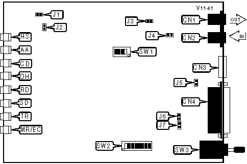
CONNECTIONS | |||
|
Purpose |
Location |
Purpose |
Location |
|
Line out |
CN1 |
RS-232/422 |
CN4 |
|
Line in |
CN2 |
Power switch |
SW3 |
|
DC power |
CN3 | ||
|
CTS SIGNAL | |
|
Setting |
SW2/1 |
| » CTS normal |
Off |
| CTS forced high |
On |
|
DCD SIGNAL | |
|
Setting |
SW2/2 |
| » DCD normal |
Off |
| DCD forced high |
On |
|
DSR SIGNAL | |
|
Setting |
SW2/3 |
| » DSR normal |
Off |
| DSR forced high |
On |
|
AT | |
|
Setting |
SW2/4 |
| » AT command set enabled |
Off |
| At command set disabled |
On |
|
LEASED LINE WIRE TYPE | |
|
Setting |
SW2/5 |
| » Two wire |
Off |
| Four wire |
On |
|
RESET | |
|
Setting |
SW2/6 |
|
Asynchronous |
On |
|
Synchronous |
Off |
|
Note: Set to on before powering modem. | |
|
DTR SIGNAL | |
|
Setting |
SW2/7 |
| » DTE sends DTR signal |
Off |
| Modem sends DTR signal |
On |
|
SIGNAL LEVEL | |
|
Setting |
J5 |
|
Signal ground normal |
Open |
|
Set signal ground equal to chassis ground |
Closed |
|
RECEIVE CLOCK | |
|
Setting |
J6 |
| » Receive clock on pin 17 disabled |
Open |
| Receive clock on pin 17 enabled |
Closed |
|
TRANSMIT CLOCK | |
|
Setting |
J7 |
| » Transmit clock on pin 15 disabled |
Open |
| Transmit clock on pin 15 enabled |
Closed |
|
FACTORY CONFIGURED SETTINGS | |
|
JUMPER |
SETTING |
|
J1 |
Open |
|
J2 |
Open |
|
J3 |
Open |
|
J4 |
Open |
|
SW2/8 |
N/A |
|
SW1 |
Not used (may not exist on all boards) |
|
DIAGNOSTIC LED(S) | ||||
|
LED |
Color |
Status |
Mode |
Condition |
|
HS |
Green |
On |
N/A |
Modem is operating at 7200bps or faster |
|
HS |
Red |
On |
N/A |
Modem is operating at 1200bps or 2400bps |
|
HS |
Green/Red |
Blinking |
N/A |
E-Mail messages stored |
|
HS |
N/A |
Off |
N/A |
Modem is operating at slower than 1200bps |
|
AA |
Red |
On |
Off-line |
Auto-answer enabled |
|
AA |
Red |
Off |
Off-line |
Auto-answer disabled |
|
AA |
N/A |
Blinking |
Off-line |
Phone is ringing |
|
AA |
Green |
On |
On-line |
Modem is using TCM modulation |
|
AA |
Green |
Blinking |
On-line |
Modem is training TCM modulation |
|
AA |
Red |
On |
On-line |
Modem is using QAM or FSK modulation |
|
AA |
Red |
Blinking |
On-line |
Modem is training QAM or FSK modulation |
|
AA |
Green/Red |
Blinking |
On-line |
Remote modem has initiated a retrain |
|
AA |
Green/Off |
Blinking |
On-line |
Local modem has initiated a retrain |
|
CD |
Red |
On |
N/A |
Carrier signal detected |
|
CD |
Red |
Off |
N/A |
Carrier signal not detected |
|
OH |
Red |
On |
N/A |
Modem is off-hook |
|
OH |
Red |
Off |
N/A |
Modem is on-hook |
|
RD |
Red |
On |
N/A |
Modem is receiving data |
|
RD |
Red |
Off |
N/A |
Modem is not receiving data |
|
SD |
Red |
On |
N/A |
Modem is transmitting data |
|
SD |
Red |
Off |
N/A |
Modem is not transmitting data |
|
TR |
Red |
On |
N/A |
DTR signal is high |
|
TR |
Red |
Off |
N/A |
DTR signal is low |
|
MR/EC |
Red |
On |
Off-line |
Power on |
|
MR/EC |
Red |
Blinking |
Off-line |
Off-line diagnostic test has failed |
|
MR/EC |
N/A |
Off |
Off-line |
Power off |
|
MR/EC |
Red |
Blinking |
On-line |
On-line diagnostic test in progress OR Modem is in ROAD mode |
|
MR/EC |
Green |
On |
On-line |
Error correction activated |
|
MR/EC |
Green |
Blinking |
On-line |
Error correction activated and modem is in ROAD mode |
|
MR/EC |
N/A |
Off |
On-line |
Error correction disabled |
Proprietary Command Set
|
APPEND CARRIAGE RETURN | |
|
Type: |
Configuration |
|
Format: |
AT [cmds] %Gn [cmds] |
|
Example: |
AT %G1 &W <CR> |
|
Description: |
Appends carriage return to result codes. |
|
Command |
Function |
| %G0 |
Append carriage return disabled. |
| » %G1 |
Append carriage return enabled. |
|
BELL 202 | |||
|
Format |
AT [cmds] S70=n [cmds] | ||
|
Example: |
ATS70=4<CR> | ||
|
Default: |
Unidentified | ||
|
Range: |
0 -4 | ||
|
Unit: |
Bit-mapped | ||
|
Description: |
Disables bell 202 mode. | ||
|
Bit |
Value |
Function | |
|
0 |
0 |
Not used. | |
|
1 |
0 |
Not used. | |
|
2 |
0 1 |
Bell 202 enabled Bell 202 disabled | |
|
CHARACTER LENGTH | |
|
Type: |
Configuration |
|
Format: |
AT [cmds] \Fn [cmds] |
|
Example: |
AT \F3 <CR> |
|
Description: |
Sets length of character. |
| Command |
Function |
| » \F0 |
8 data bits, 1 stop bit, null parity. |
| \F1 |
8 data bits, 1 stop bit, odd parity. |
| \F2 |
8 data bits, 1 stop bit, even parity. |
| \F3 |
8 data bits, 2 stop bits, null parity. |
| \F4 |
7 data bits, 1 stop bit, null parity. |
| \F5 |
7 data bits, 1 stop bit, odd parity. |
| \F6 |
7 data bits, 1 stop bit, even parity. |
| \F7 |
7 data bits, 2 stop bits, null parity. |
| \F8 |
7 data bits, 2 stop bits, odd parity. |
| \F9 |
7 data bits, 2 stop bits, even parity. |
| \F10 |
Set character length to register S13. |
|
COMMUNICATION PROTOCOL | |
|
Type: |
Configuration |
|
Format: |
AT [cmds] Bn [cmds] |
|
Example: |
AT B1 %B5 <CR> |
|
Description: |
Selects the communication protocol for data calls. |
| Command |
Function |
| » B1 |
Bell protocols. |
| B0 |
ITU-T protocols. |
|
COMPRESSION | |
|
Type: |
Configuration |
|
Format: |
AT %Cn |
|
Example: |
AT %C0 *Y1 <CR> |
|
Description: |
Selects data compression. |
| Command |
Function |
| » %C0 |
Data compression disabled. |
| %C1 |
Data compression enabled. |
|
CONNECT MODE | |
|
Type: |
Configuration |
|
Format: |
AT [cmds] \Nn [cmds] |
|
Example: |
AT \N1 DT555-1212 <CR> |
|
Description: |
Sets connect mode. |
|
Command |
Function |
|
\N1 |
Direct mode. |
|
\N0 |
Normal mode. |
|
\N2 |
Reliable mode. |
|
\N3 |
Auto-reliable mode. |
|
CONNECTION SPEED RESTRICT | |
|
Type: |
Configuration |
|
Format: |
AT [cmds] *Cn [cmds] |
|
Example: |
AT *C1 DT555-1212 <CR> |
|
Description: |
Limits speed of connection to last detected DTE speed or lower. |
|
Command |
Function |
|
*C0 |
Disabled. |
|
*C1 |
Enabled. |
|
DISPLAY CURRENT COMMAND STATUS | |
|
Type: |
Immediate |
|
Format: |
AT [cmds] \S [cmds] |
|
Example: |
AT &Z2=9W1-303-555-1212 \S <CR> |
|
Description: |
Displays current setting of modem commands. |
|
DTR DIALING | |
|
Type: |
Configuration |
|
Format: |
AT [cmds] %Dn [cmds] |
|
Example: |
AT %D1 DT555-1212 <CR> |
|
Description: |
Turns DTR dialing on and off. |
| Command |
Function |
| » %D0 |
DTR dialing disabled. |
| %D1 |
DTR dialing enabled. |
|
ERROR CORRECTION MODE | |
|
Type: |
Configuration |
|
Format: |
AT [cmds] *Yn [cmds] |
|
Example: |
AT *Y1 %C1 <CR> |
|
Description: |
Selects active error-correction protocols. |
| Command |
Function |
| *Y0 |
Auto-detect mode. |
| » *Y1 |
MNP and V.42bis enabled. |
| *Y2 |
V.42bis only enabled. |
| *Y3 |
MNP only enabled. |
|
FLOW CONTROL | |
|
Type: |
Configuration |
|
Format: |
AT [cmds] %Fn [cmds] |
|
Example: |
AT %F1 &K3 <CR> |
|
Description: |
Selects flow control. |
|
Command |
Function |
| » %F1 |
Flow control enabled for DTE and DCE |
| %F0 |
Flow control disabled. |
| %F2 |
Flow control enabled. |
|
FLOW CONTROL PASSTHROUGH | |
|
Type: |
Configuration |
|
Format: |
AT [cmds] *Pn [cmds] |
|
Example: |
AT *P0 &W <CR> |
|
Description: |
Allows modem to act on, then transmit XON/XOFF characters. |
| Command |
Function |
| » *PO |
Passthrough enabled. |
| *P1 |
Passthrough disabled. |
|
FLOW CONTROL TYPE | |
|
Type: |
Configuration |
|
Format: |
AT [cmds] \Qn [cmds] |
|
Example: |
AT \Q0 A <CR> |
|
Description: |
Sets type of flow control used by modem. |
| Command |
Function |
| » \Q0,\Q1,\Q2 |
XON/XOFF flow control enabled. |
| \Q3 |
CTS/RTS flow control enabled. |
|
INACTIVITY TIMER | |
|
Type: |
Register |
|
Format: |
AT [cmds] \Tn [cmds] |
|
Example: |
AT\T20 <CR> |
|
Default: |
0 |
|
Range: |
0-255 |
|
Unit: |
1 second |
|
Description: |
Sets the length of time that the modem does not receive information before it disconnects. |
|
INITIALIZATION STRING | |
|
Type: |
Configuration |
|
Format: |
AT [cmds] *Vn= <cmds> |
|
Example: |
AT *V1=ATS11=45 M0 <CR> |
|
Description: |
Stores string to be executed on power up or reset. |
|
INITIALIZATION STRING DISPLAY | |
|
Type: |
Immediate |
|
Format: |
AT [cmds] *V? |
|
Example: |
AT *V? <CR> |
|
Description: |
Displays stored strings to be executed on power up or reset. |
|
LEASED LINE BACK UP STATION ID | |
|
Type: |
Configuration |
|
Format: |
AT [cmds] #En [cmds] |
|
Example: |
AT *D1 *L2 #E1 <CR> |
|
Description: |
Allows modem to send and receive leased line back up ID. |
|
Command |
Function |
| #E0 |
Disabled. |
| » #E1 |
Enabled. |
|
LEASED LINE DIAL BACKUP | |
|
Type: |
Configuration |
|
Format: |
AT [cmds] *Dn [cmds] |
|
Example: |
AT *D1 *L2 #E1 <CR> |
|
Description: |
Automatically establishes switched line connection if leased line fails |
|
Command |
Function |
| » *D0 |
Disabled. |
| *D1 |
Enabled. |
|
LEASED LINE RECEIVE ATTENUATION | |
|
Type: |
Configuration |
|
Format: |
AT [cmds] %Ln [cmds] |
|
Example: |
AT %L1 &W <CR> |
|
Description: |
Sets the attenuation for reception when in leased-line mode. |
|
Command |
Function |
| » %L2 |
0 to -26 dB |
| %L0 |
0 to -43 dB |
| %L1 |
0 to -33 dB |
| %L3 |
0 to -16 dB |
|
LEASED LINE RECOVERY DELAY | |
|
Type: |
Configuration |
|
Format: |
AT [cmds] *Ln [cmds] |
|
Example: |
AT *D1 *L2 #E1 <CR> |
|
Description: |
After leased line failure, modem attempts to reconnect after specified delay. |
|
Command | |
| » *L0 |
Disabled. |
| *L1 |
5 minute delay. |
| *L2 |
15 minute delay. |
| *L3 |
30 minute delay. |
| *L4 |
60 minute delay. |
|
LEASED LINE STATION ID RECEIVE | |
|
Type: |
Configuration |
|
Format: |
AT [cmds] #Qxxxx [cmds] |
|
Example: |
AT #Q0234567891 &W <CR> |
|
Default: |
None |
|
Range: |
ASCII |
|
Unit: |
Up to ten characters |
|
Description: |
Sets leased line backup receive station ID. |
|
LEASED LINE STATION ID TRANSMIT | |
|
Type: |
Configuration |
|
Format: |
AT [cmds] #Tn [cmds] |
|
Example: |
AT #T0234567891 &W <CR> |
|
Default: |
None |
|
Range: |
ASCII |
|
Unit: |
Up to ten characters |
|
Description: |
Sets leased line backup transmit station ID. |
|
LEASED LINE TRANSMISSION ATTENUATION | |
|
Type: |
Configuration |
|
Format: |
AT [cmds] %Tn [cmds] |
|
Example: |
AT %T12 <CR> |
|
Default: |
15 |
|
Range: |
0 - 15 |
|
Unit: |
1 dB |
|
Description: |
Sets the attenuation for transmission when in leased-line mode. |
|
LINE SPEED | |||
|
Type: |
Configuration | ||
|
Format: |
AT [cmds] %Bn [cmds] | ||
|
Example: |
AT B1 %B5 <CR> | ||
|
Description: |
Sets line speed | ||
|
Command |
Mode |
Function | |
|
%B0 |
Bell |
9600bps V.32 Trellis encoding | |
|
%B0 |
ITU-T |
9600bps V.32 Trellis encoding | |
|
%B1 |
Bell |
9600bps V.32 | |
|
%B1 |
ITU-T |
9600bps V.32 | |
|
%B2 |
Bell |
2400 bps v.22bis | |
|
%B2 |
ITU-T |
2400 bps v.22bis | |
|
%B3 |
Bell |
1200bps V.22 | |
|
%B3 |
ITU-T |
1200bps V.22 | |
|
%B4 |
Bell |
300bps V.21 | |
|
%B4 |
ITU-T |
300bps V.21 | |
|
%B5 |
Bell |
9600/2400/1200/300bps | |
|
%B5 |
ITU-T |
9600/2400/1200/300bps | |
|
%B6 |
Bell |
9600/2400/1200 | |
|
%B6 |
ITU-T |
9600/2400/1200 | |
|
%B7 |
Bell |
9600/2400 | |
|
%B7 |
ITU-T |
9600/2400 | |
|
%B8 |
Bell |
1200bps V.23 HDX | |
|
%B8 |
ITU-T |
1200bps V.23 HDX | |
|
%B9 |
ITU-T |
Transmit 1200bps, receive 75bps local serial port speed follows connect speed | |
|
%B10 |
ITU-T |
Transmit 75bps, receive 1200bps local serial port speed follows connect speed | |
|
%B11 |
ITU-T |
Transmit 1200bps, receive 75bps local serial port speed independent of connect speed | |
|
%B12 |
ITU-T |
Transmit 75bps, receive 12000bps local serial port speed independent of connect speed | |
|
NEGOTIATE LINE SPEED | |
|
Type: |
Configuration |
|
Format: |
AT [cmds] %Qn [cmds] |
|
Example: |
AT %Q1 &W <CR> |
|
Description: |
Allows modem to negotiate down to Bell 202/V.23 while in answer mode |
|
Command |
Function |
|
%Q0 |
Bell 202/V.23 mode disabled. |
|
%Q1 |
Substitute 300bps modes with Bell 202/V.23 when answering. |
|
NRZI | |
|
Type: |
Configuration |
|
Format: |
AT [cmds] &Nn [cmds] |
|
Example: |
AT &N1 O <CR> |
|
Description: |
Configures DTE non return to zero interface |
|
Command | |
|
&N0 |
NRZ command and connect modes. |
|
&N1 |
NRZI command and connect modes. |
|
&N2 |
NRZ command, NRZI connect |
|
&N3 |
NRZI command, NRZ connect |
|
PULSE MODE INTERDIGIT DELAY | |
|
Type: |
Configuration |
|
Format: |
AT [cmds] %Pn [cmds] |
|
Example: |
AT %N1 %P1 P <CR> |
|
Description: |
Sets interval between digits in pulse mode. |
|
Command |
Function |
| » %P0 |
750ms |
| %P1 |
650ms |
| %P2 |
850ms |
|
PULSES PER DIGIT | |
|
Type: |
Configuration |
|
Format: |
AT [cmds] %Nn [cmds] |
|
Example: |
AT %N1 %P1 P <CR> |
|
Description: |
Sets the number of pulses per digit dialed while in pulse mode. |
|
Command |
Function |
| » %N0 |
Digit value is number of pulses (0 digit generates 10 pulses). |
| %N1 |
Digit value minus ten pulses generated (0 digit generates 10 pulses). |
| %N2 |
Digit value plus one pulses generated (0 digit generates 1 pulse). |
|
REDIAL | |
|
Type: |
Configuration |
|
Format: |
AT [cmds] *Rn |
|
Example: |
AT *R0 <CR> |
|
Default: |
0 |
|
Range: |
0-9 |
|
Unit: |
1 redial |
|
Description: |
Automatically redials next number n times. |
|
REDIAL ABORT | |
|
Type: |
Immediate |
|
Format: |
AT [cmds] \H [cmds] |
|
Example: |
AT \H <CR> |
|
Description: |
Stops redial. |
|
REDIAL LAST NUMBER | |
|
Type: |
Immediate |
|
Format: |
AT [cmds] *R |
|
Example: |
AT *R <CR> |
|
Description: |
Redials last number dialed. |
|
RESET MODEM TO STORED PROFILE | |
|
Type: |
Immediate |
|
Format: |
AT [cmds] %Sn [cmds] |
|
Example: |
AT%S6 <CR> |
|
Description: |
Resets modem to stored profile. |
|
RESULT CODE FORMAT | |
|
Type: |
Configuration |
|
Format: |
AT [cmds] \Vn [cmds] |
|
Example: |
AT \V0 Q0 <CR> |
|
Description: |
Selects word or numeric format for information-text and result codes. |
|
Command |
Function |
|
\V1 |
Numeric format enabled. |
|
\V0 |
Verbose (word) format enabled. |
|
ROAD INITIATE | |
|
Type: |
Immediate |
|
Format: |
AT [cmds] *U [cmds] |
|
Example: |
AT *B0 *U O <CR> |
|
Description: |
Commands the modem to transmit stored Remote Access Options and Downloading key. The modem must have already connected. |
|
ROAD KEY CUSTOMIZE | |
|
Type: |
Configuration |
|
Format: |
AT [cmds] *A^x^x^x^x [cmds] |
|
Example: |
AT *A^M^H^I^I &W <CR> |
|
Description: |
Sets the key for Remote Options Access and Downloading (^ indicates ctrl key depressed). The default is ^R^O^A^D. |
|
ROAD KEY ENABLE | |
|
Type: |
Configuration |
|
Format: |
AT [cmds] *Bn [cmds] |
|
Example: |
AT *B0 *U O <CR> |
|
Description: |
Enables Remote Options Access and Downloading. |
|
Command |
Function |
| » *B0 |
R.O.A.D. disabled. |
| *B1 |
R.O.A.D. enabled. |
|
S-REGISTER DISPLAY | |
|
Type: |
Immediate |
|
Format: |
AT [cmds] %R [cmds] |
|
Example: |
AT %R &W <CR> |
|
Description: |
Display contents of all S-registers. |
|
SOFTWARE SETUP | |
|
Type: |
Configuration |
|
Format: |
AT [cmds] *Sn [cmds] |
|
Example: |
AT *S1 <CR> |
|
Description: |
Configures modem to communicate with specific communications software. |
|
Command |
Function |
| » *S0 |
Normal mode, Crosstalk compatible. |
| *S1 |
Smartcom II Ver. 3.0 compatible. |
| *S3 |
Smartcom III Ver. 1.0 compatible. |
| *S4 |
AS400 HDLC dialer EIA handler. |
|
TEST/BUSY OUT | |
|
Type: |
Configuration |
|
Format: |
AT [cmds] *Tn [cmds] |
|
Example: |
AT *T1 &W <CR> |
|
Description: |
Configures pin 25 for testing or busy out. |
|
Command |
Function |
| » *T0 |
Disabled. |
| *T1 |
Enable ALB w/self test when pin 25 is true. |
| *T2 |
Enable busy out when pin 25 is true. |
|
TIME AND DATE DISPLAY | |
|
Type: |
Immediate |
|
Format: |
AT [cmds] \D? [cmds] |
|
Example: |
AT \D0=12:30 \D1=03/26 \D? <CR> |
|
Description: |
Display time and date. |
|
TIME AND DATE SET | |
|
Type: |
Configuration |
|
Format: |
AT [cmds] \Dn=xxxx [cmds] |
|
Example: |
AT \D0=12:30 \D1=03/26 \D? <CR> |
|
Description: |
Sets time and date. |
|
Command |
Function |
|
\D0 |
Set time. |
|
\D1 |
Set date. |
|
TURBO MODE | |||
|
Format |
AT [cmds] S94;5=n [cmds] | ||
|
Example: |
ATS94;5=1 <CR> | ||
|
Default: |
None | ||
|
Range: |
0-16 | ||
|
Unit: |
Bit-mapped | ||
|
Description: |
Allows 12Kbps connection with compatible remote modem. | ||
|
Bit | Value |
Function | |
|
5 |
0 1 |
Enabled. Disabled. | |
|
V.25 | |
|
Type: |
Configuration |
|
Format: |
AT [cmds] V.25 |
|
Example: |
AT V.25 <CR> |
|
Description: |
Enables V.25bis mode. |
|
V.25bis COMMAND MODE SPEED | |
|
Type: |
Configuration |
|
Format: |
AT [cmds] *Wn [cmds] |
|
Example: |
AT *W0 &W <CR> |
|
Description: |
V.25bis mode only. DTE sets off line speed for sync command processing. |
|
Command |
Function |
| » *W0 |
Last auto baud speed, 9600bps if none. |
| *W1 |
1200bps. |
| *W2 |
2400bps. |
| *W3 |
4800bps. |
| *W4 |
9600bps. |
| *W5 |
19.2Kbps. |
| *W6 |
38.4Kbps. |
| *W7 |
Use pin 24 external clock control. |
|
V.32bis FALLBACK | |||
|
Format |
AT [cmds] S94=n [cmds] | ||
|
Example: |
ATS94=40<CR> | ||
|
Default: |
Unidentified | ||
|
Range: |
0 - 16 | ||
|
Unit: |
Bit-mapped | ||
|
Description: |
Controls limited V.32bis 12,000bps .operation | ||
|
Bit |
Value |
Function | |
|
0 |
0 |
Not used. | |
|
1 |
0 |
Not used. | |
|
2 |
0 |
Not used. | |
|
3 |
0 |
Not used. | |
|
4 |
0 |
Not used. | |
|
5 |
0 1 |
12,000bps limited V.32bis capability disabled. 12,000bps limited V.32bis capability enabled. | |
Proprietary V.25bis Command Set
|
AT COMMAND SET | |
|
Type: |
Immediate |
|
Format: |
ATC |
|
Example: |
ATC <CR> |
|
Description: |
Switch to AT command set. |
|
CALL REQUESTED NUMBER AND TRANSMIT STATION ID | |
|
Type: |
Configuration |
|
Format: |
CRI <#>;xxxx |
|
Example: |
CRI 487-3289; 1234567890 <CR> |
|
Description: |
Modem phone number, then transmits station ID after connection |
|
CLEAR STORED NUMBER | |
|
Type: |
Configuration |
|
Format: |
CLAnn |
|
Example: |
CRI 07 <CR> |
|
Description: |
Deletes number stored at memory location n. |
|
DISPLAY STORED NUMBERS | |
|
Type: |
Immediate |
|
Format: |
RLNn |
|
Example: |
RLN2 <CR> |
|
Description: |
Display insecure number in memory location n. If no number is given, all insecure numbers will be displayed. |
|
REDIAL | |
|
Type: |
Immediate |
|
Format: |
DLN |
|
Example: |
DLN <CR> |
|
Description: |
Redial last number dialed by CRN command. |
|
STATION ID SET | |
|
Type: |
Configuration |
|
Format: |
PRInnn; <#>;xxxx |
|
Example: |
PRI 011; 487-3289; 1234567890 <CR> |
|
Description: |
Records station ID |
Proprietary V.25bis Result Codes
|
STATION ID LIST | |
|
Type: |
Result code |
|
Format: |
LSIxxxx |
|
Example: |
LSI 2345678901 |
|
Description: |
Displays station ID. |
|
STORED NUMBERS LIST | |
|
Type: |
Result code |
|
Format: |
LSNxxxx |
|
Example: |
LSN 443-3388 |
|
Description: |
Displays stored numbers. xxxx may specify a memory location, phone number, or status. If no code was specified with RLN, all stored numbers are displayed. |