U.S. ROBOTICS, INC.
COURIER HST DUAL STANDARD W/ V.32BIS & ASL
|
Modem Type |
Data (synchronous/asynchronous) |
|
Maximum Data Rate |
14.4Kbps |
|
Data Bus |
External |
|
Data Modulation Protocol |
Bell 103A/212A ITU-T V.22, V.22bis, V.23, V.32, V.32bis |
|
Error Correction/Compression |
MNP5, V.42, V.42bis |
|
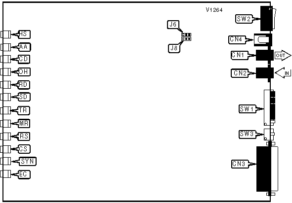
CONNECTIONS | |||
|
Purpose |
Location |
Purpose |
Location |
|
Line out |
CN1 |
DC power |
CN4 |
|
Line in |
CN2 |
Volume |
R1 |
|
RS-232/422 |
CN3 |
Power switch |
SW2 |
|
MI/MIC POLARITY | ||
| Setting |
J6 |
J8 |
| » Normal |
Pins 1 & 2 closed |
Pins 1 & 2 closed |
| Reversed |
Pins 2 & 3 closed |
Pins 2 & 3 closed |
|
TX/RX PIN ASSIGNMENT | |
| Setting |
SW3 |
|
Normal operation | » Off |
|
Reverse TX/RX pin assignments | On |
|
DTR SIGNAL | |
| Setting |
SW1/1 |
| DTR forced high |
On |
| » DTR normal |
Off |
|
RESULT CODES | |
| Setting |
SW1/2 |
| » Verbose result codes enabled |
Off |
| Numeric result codes enabled |
On |
|
RESULT CODES DISPLAY | |
| Setting |
SW1/3 |
| » Display enabled |
On |
| Display disabled |
Off |
|
ECHO COMMANDS DISPLAY | |
| Setting |
SW1/4 |
| » Local echo enabled |
Off |
| Local echo disabled |
On |
|
AUTO ANSWER | |
| Setting |
SW1/5 |
| » Modem answers on first ring |
On |
| Modem does not answer on first ring |
Off |
|
CARRIER DETECT | |
| Setting |
SW1/6 |
| » CD normal |
Off |
| CD forced high |
On |
|
RESULT CODES DISPLAY | |
| Setting |
SW1/7 |
| » Display result codes in originate and answer modes |
Off |
| Display result codes in Answer mode |
On |
|
AT COMMAND SET | |
| Setting |
SW1/8 |
| » AT command set enabled |
On |
| AT command set disabled |
Off |
|
ESCAPE CODE | |
| Setting |
SW1/9 |
| » Off |
Disconnect, go to command mode and display NO CARRIER when escape character is received |
| On |
Go to command mode and display OK result code when escape character is received |
|
USER PROFILE | |
| Setting |
SW1/10 |
| » Off |
Use stored profile |
| On |
Use factory default |
|
VOICE/DATA | |
|
Setting |
SW4 |
|
Note: for switch functions see table for register S32. | |
|
DIAGNOSTIC LED(S) | |||
|
LED |
Color |
Status |
Condition |
|
HS |
Red |
On |
Modem is operating at 4800bps or faster |
|
HS |
Red |
Off |
Modem is operating at slower than 4800bps |
|
AA |
Red |
On |
Auto-answer enabled |
|
AA |
Red |
Off |
Auto-answer disabled |
|
CD |
Red |
On |
Carrier signal detected |
|
CD |
Red |
Off |
Carrier signal not detected |
|
OH |
Red |
On |
Modem is off-hook |
|
OH |
Red |
Off |
Modem is on-hook |
|
RD |
Red |
On |
Modem is receiving data |
|
RD |
Red |
Off |
Modem is not receiving data |
|
TD |
Red |
On |
Modem is transmitting data |
|
TD |
Red |
Off |
Modem is not transmitting data |
|
TR |
Red |
On |
DTR signal is high |
|
TR |
Red |
Off |
DTR signal is low |
|
MR |
Red |
On |
Power is on |
|
MR |
Red |
Off |
Power is off |
|
MR |
Red |
Blinking |
Modem is retraining or in test mode |
|
RS |
Red |
On |
RTS signal is high |
|
RS |
Red |
Off |
RTS signal is low |
|
CS |
Red |
On |
CTS signal is high |
|
CS |
Red |
Off |
CTS signal is low |
|
EC |
Red |
On |
Error control enabled |
|
EC |
Red |
Off |
Error control disabled |
|
EC |
Red |
Blinking |
Modem is retransmitting data |
|
SYN |
Red |
On |
Synchronous mode |
|
SYN |
Red |
Off |
Asynchronous mode |
Proprietary AT Command Set
|
BIT-MAPPED REGISTER S13 | |||
|
Format |
AT [cmds] S13=n [cmds] | ||
|
Example: |
ATS13=139 <CR> | ||
|
Default: |
0 | ||
|
Range: |
0 - 255 | ||
|
Unit: |
Bit-mapped | ||
|
Description: |
Controls DTR reset, DTR dialing, auto answer, result code delay, reset dialing, HST and MNP3. | ||
|
Bit | Value |
Function | |
|
0 | » 0 1 |
DTR normal. Reset on low DTR. | |
|
1 | » 0 1 |
Auto answer operation normal. When ring detected, enter originate mode and listen for answer tone. | |
|
2 | » 0 1 |
Pause 250 msec. before displaying result codes. Display result codes immediately. | |
|
3 | » 0 1 |
DTR dialing disabled. DTR dialing enabled. | |
|
4 | » 0 1 |
Reset dialing disabled. Reset dialing enabled. | |
|
5 | » 0 1 |
HST enabled. HST disabled. | |
|
6 | » 0 1 |
MNP 3 enabled. MNP 3 disabled. | |
|
BIT-MAPPED REGISTER S15 | |||
|
Format: |
AT [cmds] S15=n [cmds] | ||
|
Example: |
ATS15=139 <CR> | ||
|
Default: |
0 | ||
|
Range: |
0 - 255 | ||
|
Unit: |
Bit-mapped | ||
|
Description: |
Controls HST high frequency equalization, online fallback, back channel, non-error-correcting mode buffer, MNP4, BS/DEL switch, and MNP compliance. | ||
|
Bit | Value |
Function | |
|
0 | » 0 1 |
HST high frequency equalization enabled. HST high frequency equalization disabled. | |
|
1 | » 0 1 |
Online fallback enabled. Online fallback disabled. | |
|
2 | » 0 1 |
450bps back channel enabled. 450bps back channel disabled. | |
|
3 | » 0 1 |
Non-error-correcting mode transmit buffer set to 1.5KB. Non-error-correcting mode transmit buffer set to 128 bytes. | |
|
4 | » 0 1 |
MNP 4 enabled. MNP 4 disabled. | |
|
5 | » 0 1 |
Use backspace key for delete disabled. Use backspace key for delete enabled. | |
|
6 | » 0 1 |
MNP normal. MNP adjusted for non compliant modems. | |
|
7 | » 0 1 |
Proprietary network compatibility disabled. Proprietary network compatibility enabled. | |
|
BIT-MAPPED REGISTER S27 | |||
|
Format: |
AT [cmds] S27=n [cmds] | ||
|
Example: |
ATS27=139 <CR> | ||
|
Default: |
0 | ||
|
Range: |
0 - 191 | ||
|
Unit: |
Bit-mapped | ||
|
Description: |
Controls V.21, V.32 encoding and modulation, V.42 answer tone and handshake, and 9600 result codes. | ||
|
Bit | Value |
Function | |
|
0 | » 0 1 |
V.21 disabled. V.21 enabled. | |
|
1 | » 0 1 |
V.32 trellis coding disabled. V.32 trellis coding enabled. | |
|
2 | » 0 1 |
V.32 modulation enabled. V.32 modulation disabled. | |
|
3 | » 0 1 |
2100Hz answer tone enabled. 2100Hz answer tone disabled. | |
|
5, 4 | » 00 01 10 11 |
V.42 detect, LAPM and MNP enabled. V.42 detect and LAPM enabled. MNP enabled. LAPM enabled. | |
|
6 | » 0 |
Not used. | |
|
7 | » 0 1 |
Actual result codes displayed. Force 9600 result codes. | |
|
BREAK LENGTH | |
|
Type: |
Register |
|
Format: |
AT [cmds] S21=n [cmds] |
|
Example: |
ATS21=20 <CR> |
|
Default: |
10 |
|
Range: |
Unidentified |
|
Unit: |
10 ms |
|
Description: |
Sets the length of error control mode breaks sent from DCE to DTE. |
|
BREAK TYPE | |
|
Type: |
Configuration |
|
Format: |
AT [cmds] &Yn [cmds] |
|
Example: |
AT &Y0 <CR> |
|
Description: |
Configures action of break signal. |
| Command |
Function |
| &Y0 |
Break empties buffer. |
| » &Y1 |
Break empties buffer and is sent immediately. |
| &Y2 |
Break does not empty buffer and is sent immediately. |
|
COMPRESSION | |
|
Type: |
Configuration |
|
Format: |
AT [cmds] &Kn [cmds] |
|
Example: |
AT &K1 <CR> |
|
Description: |
Controls data compression. |
| Command |
Function |
| &K0 |
Data compression disabled. |
| » &K1 |
Data compression disabled when serial port is locked. |
| &K2 |
MNP5 enabled/MNP4 enabled. |
| &K3 |
MNP 5 disabled. |
|
CONNECTION SPEED UPPER LIMIT | |
|
Type: |
Configuration |
|
Format: |
AT [cmds] &Nn [cmds] |
|
Example: |
AT &N1 DT555-1212 <CR> |
|
Description: |
Sets required connection speed if &U is set to 0. Otherwise, sets fastest allowed connection speed. |
| Command |
Function |
| » &N0 |
Variable. |
| &N1 |
300bps |
| &N2 |
1200bps |
| &N3 |
2400bps |
| &N4 |
4800bps |
| &N5 |
7200bps |
| &N6 |
9600bps |
| &N7 |
12Kbps |
| &N8 |
14.4Kbps |
|
EXTENDED RESULT CODES | |
|
Type: |
Configuration |
|
Format: |
AT [cmds] &An [cmds] |
|
Example: |
AT &A1 %C1 <CR> |
|
Description: |
Selects extended result codes. |
| Command |
Function |
| &A0 |
Extended result codes disabled. |
| &A1 |
ARQ result codes enabled. |
| &A2 |
V.32 result code enabled. |
| » &A3 |
Error control and compression result codes enabled. |
|
FLOW CONTROL CHARACTER - XON | |
|
Type: |
Register |
|
Format: |
AT [cmds] S22=n [cmds] |
|
Example: |
ATS22=20 <CR> |
|
Default: |
17 |
|
Range: |
11-127 |
|
Unit: |
ASCII |
|
Description: |
Sets the character used to represent XON. |
|
FLOW CONTROL CHARACTER - XOFF | |
|
Type: |
Register |
|
Format: |
AT [cmds] S23=n [cmds] |
|
Example: |
ATS23=20 <CR> |
|
Default: |
19 |
|
Range: |
11-127 |
|
Unit: |
ASCII |
|
Description: |
Sets the character used to represent XOFF. |
|
FLOW CONTROL PASSTHROUGH | |
|
Type: |
Configuration |
|
Format: |
AT [cmds] &In [cmds] |
|
Example: |
AT &I0 &W <CR> |
|
Description: |
Allows modem to act on, then transmit XON/XOFF characters. |
| Command |
Function |
| » &I0 |
Software flow control disabled. |
| &I1 |
XON/XOFF passthrough enabled. |
| &I2 |
XON/XOFF passthrough disabled. |
| &I3 |
ENQ/ACK protocol used in host mode. |
| &I4 |
ENQ/ACK protocol used in terminal mode. |
| &I5 |
XON/XOFF passthrough disabled in ARQ mode, XON/XOFF to remote modem. |
|
FLOW CONTROL TYPE | |
|
Type: |
Configuration |
|
Format: |
AT [cmds] &Hn [cmds] |
|
Example: |
AT &H0 A <CR> |
|
Description: |
Sets type of flow control used by modem. |
| Command |
Function |
| &H0 |
Flow control disabled. |
| » &H1 |
CTS/RTS flow control enabled. |
| &H2 |
XON/XOFF flow control enabled. |
| &H3 |
CTS/RTS and XON/XOFF flow control enabled. |
|
HELP SCREENS | |
|
Type: |
Immediate |
|
Format: |
AT <prefix>$ |
|
Example: |
AT &$ <CR> |
|
Description: |
Shows command help screens for all commands beginning with the given prefix, or no prefix if none is given. |
|
Command |
Function |
|
$ |
Shows AT help screen. |
|
&$ |
Shows AT& help screen. |
|
D$ |
Shows ATD help screen. |
|
S$ |
Shows S-register help screen. |
|
INACTIVITY TIMER | |
|
Type: |
Register |
|
Format: |
AT [cmds] S19=n [cmds] |
|
Example: |
ATS19=20 <CR> |
|
Default: |
0 |
|
Range: |
Unidentified |
|
Unit: |
1 minute |
|
Description: |
Sets the length of time that the modem does not receive information before it disconnects. |
|
NETWORK ACCESS | |
|
Type: |
Configuration |
|
Format: |
AT [cmds] %Rn [cmds] |
|
Example: |
AT %R1 &W <CR> |
|
Description: |
Used with USR network management system. |
| Command |
Function |
| » %R0 |
Network access disabled. |
| %R1 |
Network access enabled. |
|
REPEAT COMMAND STRING | |
|
Type: |
Configuration |
|
Format: |
AT [cmds] > [cmds] |
|
Example: |
AT *D1 > #E1 <CR> |
|
Description: |
Causes modem to repeat command string until a keyboard key is pressed. |
|
REPORT INFORMATION | |
|
Type: |
Immediate |
|
Format: |
AT [cmds] In [cmds] |
|
Example: |
AT I1 O <CR> |
|
Description: |
Displays modem properties. |
|
Command |
Function |
|
I0 |
Reports product code. |
|
I1 |
Reports ROM checksum result. |
|
I2 |
Reports RAM checksum result. |
|
I3 |
Reports call duration. |
|
I4 |
Reports current command settings. |
|
I5 |
Reports current NVRAM settings. |
|
I6 |
Reports current connection’s statistics. |
|
I7 |
Reports configuration. |
|
STATUS REGISTER BIT | |
|
Type: |
Configuration |
|
Format: |
Read: AT [cmds] Sn.m=0 or 1 [cmds] Write: AT [cmds] Sn.m=? [cmds] |
|
Example: |
AT S40.4=1 S51.3? <CR> |
|
Description: |
Sets/clears or reads bit m of register n. |
|
TEST MODES | |||
|
Format |
AT [cmds] S16=n [cmds] | ||
|
Example: |
ATS16=32 <CR> | ||
|
Default: |
0 | ||
|
Range: |
0 - 15 | ||
|
Unit: |
Bit-mapped | ||
|
Description: |
Enables loopback tests. | ||
|
Bit | Value |
Function | |
|
0 | » 0 1 |
Analog loopback test disabled. Analog loopback test enabled. | |
|
1 | » 0 1 |
Dial test disabled. Dial test enabled. | |
|
2 | » 0 1 |
Test pattern disabled. Test pattern enabled. | |
|
3. | » 0 1 |
Remote digital loopback test disabled. Remote digital loopback test enabled. | |
|
TIME DISPLAY | |
|
Type: |
Immediate |
|
Format: |
AT [cmds] Kn [cmds] |
|
Example: |
AT K1 *L2 #E1<CR> |
|
Description: |
Displays the current call time or clock time. |
| Command |
Function |
| » K0 |
Display length of last call. |
| K1 |
Display actual time. |
|
TOUCH TONE RECOGNITION | |
|
Type: |
Configuration |
|
Format: |
AT [cmds] %Tn [cmds] |
|
Example: |
AT %T &W <CR> |
|
Description: |
Controls recognition of touch tones while off hook. |
|
V.32 AND V.32bis MODULATIONS | |||
|
Format: |
AT [cmds] S34=n [cmds] | ||
|
Example: |
ATS34=139 <CR> | ||
|
Default: |
6 | ||
|
Range: |
0 - 63 | ||
|
Unit: |
Bit-mapped | ||
|
Description: |
Controls V.32 and V.32bis modulations. | ||
|
Bit |
Value |
Function | |
|
0 | » 0 1 |
V.32bis enabled. V.32bis disabled. | |
|
1 | » 0 1 |
Enhanced V.32bis enabled. Enhanced V.32bis disabled. | |
|
2 | » 0 1 |
Enhanced V.32bis retrain enabled. Enhanced V.32bis retrain disabled. | |
|
3 | » 0 1 |
V.23 disabled. V.23 enabled. | |
|
4 | » 0 1 |
MR LED normal. MR LED reflects DSR signal. | |
|
5 | » 0 1 |
MI/MIC disabled. MI/MIC enabled. | |
|
V.32 HANDSHAKE TIME | |
|
Type: |
Register |
|
Format: |
AT [cmds] S28=n [cmds] |
|
Example: |
ATS28=20 <CR> |
|
Default: |
8 |
|
Range: |
0-255 |
|
Unit: |
.1 second |
|
Description: |
Sets length of V.32 handshake. |
|
VOICE/DATA SWITCH | |
|
Type: |
Register |
|
Format: |
AT [cmds] S32=n [cmds] |
|
Example: |
ATS32=6 <CR> |
|
Default: |
1 |
|
Unit: |
1-7 |
|
Description: |
Controls the function of SW4. |
| Command |
Function |
| 0 |
Disabled. |
| » 1 |
Switch between voice and originate mode. |
| 2 |
Switch between voice and answer mode. |
| 3 |
Redial. |
| 4 |
Dial number stored at position 0. |
| 5 |
Enable and disable Auto Answer. |
| 6 |
Reset. |
| 7 |
Start remote digital loopback test. |