ZYXEL COMMUNICATIONS CORPORATION
OMNI TA128, OMNI TA128U
|
Card Type |
ISDN TA |
|
Chipset |
Siemens |
|
ISDN Protocol |
V.110, V.120, X.75, PPP |
|
Switch Type |
5ESS, DMS100, 1TR6, EWSD, DSS1, NI-1 |
|
Transfer Rate |
64Kbps x 2 |
|
Data Bus |
Serial |
|
Error Correction/Compression |
V.42bis |
|
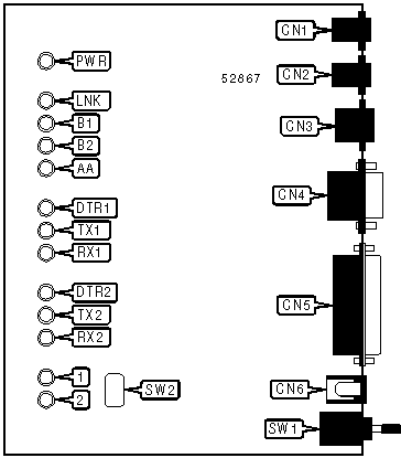
CONNECTIONS | |||
|
Function |
Label |
Function |
Label |
|
Analog line 1 in |
CN1 |
Serial port 1 |
CN5 |
|
Analog line 2 in |
CN2 |
DC power in |
CN6 |
|
ISDN line out |
CN3 |
Power switch |
SW1 |
|
Serial port 2 |
CN4 |
Auto-dial switch |
SW2 |
Note: Pressing the auto-dial switch while connected will disconnect the call. | |||
|
DIAGNOSTIC LED(S) (POWER-UP) | |||
|
LED |
Color |
Status |
Condition |
|
LNK |
Unidentified |
On |
TA is testing memory |
|
LNK |
Unidentified |
Blinking |
Memory test failed |
|
B1 |
Unidentified |
On |
TA is testing ISDN controller interface |
|
B1 |
Unidentified |
Blinking |
ISDN controller interface test failed |
|
B2 |
Unidentified |
On |
TA is testing ISDN controller functions |
|
B2 |
Unidentified |
Blinking |
ISDN controller function test failed |
|
AA |
Unidentified |
On |
TA is testing HDLC functions |
|
AA |
Unidentified |
Blinking |
HDLC function test failed |
|
LNK |
Unidentified |
On |
All tests passed |
Note: On power-up, the LEDs should indicate the tests in progress in the order indicated above. A blinking LED or any pattern other than the ones shown above indicate an error. The final indication should remain lit for one-half of one second. | |||
|
DIAGNOSTIC LED(S) (NORMAL OPERATION) | |||
|
LED |
Color |
Status |
Condition |
|
PWR |
Unidentified |
On |
Power is on |
|
PWR |
Unidentified |
Off |
Power is off |
|
LNK |
Unidentified |
On |
Physical ISDN layer active |
|
LNK |
Unidentified |
Off |
Physical ISDN layer inactive |
|
LNK |
Unidentified |
Blinking |
D-channel link layer in multi-frame mode |
|
B1 |
Unidentified |
On |
B1 channel connected |
|
B1 |
Unidentified |
Off |
B1 channel not connected |
|
B1 |
Unidentified |
Random blink |
B1 channel is retransmitting packets |
|
B1 |
Unidentified |
1 blink |
B1 channel is protected by single DES mode encryption |
|
B1 |
Unidentified |
3 blinks |
B1 channel is protected by triple DES mode encryption |
|
B2 |
Unidentified |
On |
B2 channel connected |
|
B2 |
Unidentified |
Off |
B2 channel not connected |
|
B2 |
Unidentified |
Random blink |
B2 channel is retransmitting packets |
|
B2 |
Unidentified |
1 blink |
B2 channel is protected by single DES mode encryption |
|
B2 |
Unidentified |
3 blinks |
B2 channel is protected by triple DES mode encryption |
|
AA |
Unidentified |
On |
Auto-answer enabled |
|
AA |
Unidentified |
Off |
Auto-answer disabled |
|
AA |
Unidentified |
Blinking |
Phone is ringing |
|
DTR1 |
Unidentified |
On |
DTR signal of serial port 1 is high |
|
DTR1 |
Unidentified |
Off |
DTR signal of serial port 1 is low |
|
TX1 |
Unidentified |
Blinking |
Serial port 1 is transmitting data to TA |
|
TX1 |
Unidentified |
Off |
Serial port 1 is not transmitting data to TA |
|
RX1 |
Unidentified |
Blinking |
Serial port 1 is receiving data from TA |
|
RX1 |
Unidentified |
Off |
Serial port 1 is not receiving data from TA |
|
DIAGNOSTIC LED(S) (NORMAL OPERATION, CON’T) | |||
|
LED |
Color |
Status |
Condition |
|
DTR2 |
Unidentified |
On |
DTR signal of serial port 2 is high |
|
DTR2 |
Unidentified |
Off |
DTR signal of serial port 2 is low |
|
TX2 |
Unidentified |
Blinking |
Serial port 2 is transmitting data to TA |
|
TX2 |
Unidentified |
Off |
Serial port 2 is not transmitting data to TA |
|
RX2 |
Unidentified |
Blinking |
Serial port 2 is receiving data from TA |
|
RX2 |
Unidentified |
Off |
Serial port 2 is not receiving data from TA |
|
1 |
Unidentified |
On |
Analog line 1 is off-hook |
|
1 |
Unidentified |
Off |
Analog line 1 is on-hook |
|
2 |
Unidentified |
On |
Analog line 2 is off-hook |
|
2 |
Unidentified |
Off |
Analog line 2 is on-hook |
|
SUPPORTED STANDARD COMMANDS |
|
Basic AT Commands |
|
+++, ‘comma’, A/ |
|
A, E, L, M, O, Q, V, X, Z |
|
&C, &D, &F, &H, &S, &W, &Z |
|
S-Registers |
|
S0, S1, S2, S3, S4, S5, S7, S8, S16, S21, S23, S25, S31, S32 |
Note: See MHI documentation for complete information. |
Proprietary AT Command Set
|
AUTO-CALLBACK | ||
|
Type: |
Configuration | |
|
Format: |
AT [cmds] *GCn [cmds] | |
|
Description: |
Selects the auto-callback feature. The modem will compare the caller ID information to the five auto-callback numbers stored with the *HC command. If one of them matches, the modem will reject the call before it connects and call that number back. | |
|
Command |
Function | |
|
í *GC0 |
Auto-callback disabled. | |
|
*GC1 |
Auto-callback enabled. | |
|
AUTO-CALLBACK NUMBER DISPLAY | |
|
Type: |
Immediate |
|
Format: |
AT [cmds] *VC [cmds] |
|
Description: |
Displays all auto-callback numbers. |
|
AUTO-CALLBACK NUMBER SET | |
|
Type: |
Configuration |
|
Format: |
AT [cmds] *HCn= <#> |
|
Description: |
Sets auto-callback number n to the number specified. n must be between 0 and 4. |
|
BIT-MAPPED REGISTER S24 | ||
|
Format |
AT [cmds] S24=n [cmds] | |
|
Default: |
Unidentified | |
|
Range: |
0-63 | |
|
Description: |
Controls ring volume, speaker volume, and speaker control for analog line DTMF tone generation. | |
|
Bit |
Value |
Function |
|
1,0 |
00 01 10 11 |
Ring volume off. Ring volume low. Ring volume medium. Ring volume high. |
|
2 |
0 1 |
DTMF tones from analog line 1 follow setting of M command. DTMF tones from analog line 1 audible regardless of setting of M command. |
|
3 |
0 1 |
DTMF tones from analog line 2 follow setting of M command. DTMF tones from analog line 2 audible regardless of setting of M command. |
|
5,4 |
00 01 10 11 |
Speaker volume off. Speaker volume low. Speaker volume medium. Speaker volume high. |
|
BIT-MAPPED REGISTER S118 | ||
|
Format: |
AT [cmds] S118=n [cmds] | |
|
Default: |
Unidentified | |
|
Range: |
0 - 245 | |
|
Description: |
Controls dial-in mode, default line speed, low-speed service type, and analog call acceptance. | |
|
Bit |
Value |
Function |
|
0 |
0 1 |
Dial-in calls may be answered. Dial-in calls may not be answered. |
|
1 |
0 |
Not used. |
|
2 |
0 1 |
Use 64Kbps speed for ISDN. Use 56Kbps speed for ISDN. |
|
3 |
0 |
Not used. |
|
4 |
í 01 |
Use 3.1KHz service for analog line 2. Use voice service for analog line 2. |
|
5 |
í 01 |
Use 3.1KHz service for analog line 1. Use voice service for analog line 1. |
|
6 |
í 01 |
All analog calls will be answered. Only analog calls with matching MSN will be answered. |
|
7 |
í 01 |
Incoming analog calls will be answered. Incoming analog calls will be ignored. |
|
CONFIGURATION PROFILES | |
|
Type: |
Immediate |
|
Format: |
AT [cmds] &Vn [cmds] |
|
Description: |
Displays active and stored configuration profiles. |
|
Command |
Function |
|
&V0 |
Displays current settings. |
|
&V1 |
Displays profile 0. |
|
&V2 |
Displays profile 1. |
|
&V3 |
Displays profile 2. |
|
&V4 |
Displays profile 3. |
|
&V5 |
Displays factory defaults. |
|
&V6 |
Displays analog line 1 settings. |
|
&V7 |
Displays analog line 2 settings. |
|
HOOK CONTROL | ||
|
Type: |
Immediate | |
|
Format: |
AT [cmds] Hn [cmds] | |
|
Description: |
Hangs up ISDN and analog lines. | |
|
Command |
Function | |
|
H0 |
Hangs up line currently in use. | |
|
H3 |
Hangs up analog line 1. | |
|
H4 |
Hangs up analog line 2. | |
|
I-FIELD DATA LENGTH | |
|
Type: |
Register |
|
Format: |
AT [cmds] S114=n S115=n [cmds] |
|
Default: |
Unidentified |
|
Range: |
0-65535 |
|
Unit: |
N/A |
|
Description: |
These registers set the data length for the I-field. S114 stores the Most Significant Byte, and S115 stores the Least Significant Byte. To set the correct value for S114, use the formula S114 = INT(value/256). To set S115, use the formula S115 = value - S114 * 256. |
|
LOCAL SERIAL PORT SPEED | |
|
Type: |
Register |
|
Format: |
AT [cmds] S20=n [cmds] |
|
Description: |
Sets the speed of the local serial port. |
|
Command |
Function |
|
S20=0 |
Sets 921.6Kbps speed. |
|
S20=1 |
Sets 460.8Kbps speed. |
|
S20=2 |
Sets 230.4Kbps speed. |
|
í S20=3 |
Sets 115.2Kbps speed. |
|
S20=8 |
Sets 57.6Kbps speed. |
|
S20=9 |
Sets 38.4Kbps speed. |
|
S20=10 |
Sets 19.2Kbps speed. |
|
S20=11 |
Sets 9600bps speed. |
|
S20=12 |
Sets 4800bps speed. |
|
S20=13 |
Sets 2400bps speed. |
|
S20=14 |
Sets 1200bps speed. |
|
LOCAL SERIAL PORT SPEED ON AUTO-ANSWER | |
|
Type: |
Register |
|
Format: |
AT [cmds] S18=n [cmds] |
|
Description: |
Sets serial port speed when modem auto-answers an incoming call. |
|
Command |
Function |
|
í 0 |
Auto-detect current speed. |
|
1 |
Sets 921.6Kbps speed. |
|
2 |
Sets 460.8Kbps speed. |
|
3 |
Sets 230.4Kbps speed. |
|
4 |
Sets 115.2Kbps speed. |
|
9 |
Sets 57.6Kbps speed. |
|
10 |
Sets 38.4Kbps speed. |
|
11 |
Sets 19.2Kbps speed. |
|
12 |
Sets 9600bps speed. |
|
13 |
Sets 4800bps speed. |
|
14 |
Sets 2400bps speed. |
|
15 |
Sets 1200bps speed. |
|
METERING PULSE | ||
|
Format |
AT [cmds] S89=n [cmds] | |
|
Default: |
Unidentified | |
|
Range: |
0-96 | |
|
Description: |
Controls the generation of metering pulses on the analog adapters. | |
|
Bit |
Value |
Function |
|
5 |
0 1 |
Metering pulse for analog line 1 disabled. Metering pulse for analog line 1 enabled. |
|
6 |
0 1 |
Metering pulse for analog line 2 disabled. Metering pulse for analog line 2 enabled. |
|
PORT ASSIGNMENTS | ||
|
Type: |
Configuration | |
|
Format: |
AT [cmds] S125=n [cmds] | |
|
Description: |
Selects which ports may be in use. | |
|
Command |
Function | |
|
í S125=0 |
Serial port 2 disabled; analog port 2 enabled. | |
|
S125=1 |
Serial port 2 enabled; analog port 2 disabled. | |
|
PPP IDLE OUT PREVENTION | |
|
Type: |
Register |
|
Format: |
AT [cmds] S124=n [cmds] |
|
Default: |
0 |
|
Range: |
0-255 |
|
Unit: |
1 second |
|
Description: |
Sends an empty packet after being idle for the time specified to avoid disconnection on PPP connections. |
|
REPORT INFORMATION | ||
|
Type: |
Immediate | |
|
Format: |
AT [cmds] In [cmds] | |
|
Description: |
Returns requested information about the TA. | |
|
Command |
Function | |
|
I0 |
Displays product code. | |
|
I1 |
Displays product information and ROM checksum. | |
|
I9 |
Displays Plug-N-Play code. | |
|
SERIAL PORT 2 DATA FORMAT | ||
|
Type: |
Configuration | |
|
Format: |
AT [cmds] *Nn [cmds] | |
|
Description: |
Sets the parity used for the second serial port. | |
|
Command |
Function | |
|
*N0 |
8 data bits, no parity, 1 stop bit. | |
|
*N1 |
7 data bits, even parity, 1 stop bit. | |
|
*N2 |
7 data bits, odd parity, 1 stop bit. | |
|
SERIAL PORT 2 DATA FORMAT | ||
|
Type: |
Configuration | |
|
Format: |
AT [cmds] S46=n [cmds] | |
|
Description: |
Sets the parity used for the second serial port. | |
|
Command |
Function | |
|
S46=0 |
8 data bits, no parity, 1 stop bit. | |
|
S46=1 |
7 data bits, even parity, 1 stop bit. | |
|
S46=2 |
7 data bits, odd parity, 1 stop bit. | |
|
SERIAL PORT 2 FLOW CONTROL | ||
|
Type: |
Configuration | |
|
Format: |
AT [cmds] *Mn [cmds] | |
|
Description: |
Selects the flow control used on the second serial port. | |
|
Command |
Function | |
|
*M0 |
Flow control disabled. | |
|
*M1 |
RTS/CTS flow control enabled. | |
|
*M2 |
XON/XOFF flow control enabled. | |
|
SERIAL PORT 2 FLOW CONTROL | ||
|
Type: |
Configuration | |
|
Format: |
AT [cmds] S45=n [cmds] | |
|
Description: |
Selects the flow control used on the second serial port. | |
|
Command |
Function | |
|
S45=0 |
Flow control disabled. | |
|
S45=1 |
RTS/CTS flow control enabled. | |
|
S45=2 |
XON/XOFF flow control enabled. | |
|
SERIAL PORT 2 SPEED | ||
|
Type: |
Configuration | |
|
Format: |
AT [cmds] *An [cmds] | |
|
Description: |
Sets the speed of the second serial port. | |
|
Note: |
This command may only be issued through port 1. | |
|
Command |
Function | |
|
í *A1 |
Set serial port speed to 115.2Kbps. | |
|
*A2 |
Set serial port speed to 76.8Kbps. | |
|
*A3 |
Set serial port speed to 57.6Kbps. | |
|
*A4 |
Set serial port speed to 38.4Kbps. | |
|
*A5 |
Set serial port speed to 19.2Kbps. | |
|
*A6 |
Set serial port speed to 9600bps. | |
|
*A7 |
Set serial port speed to 2400bps. | |
|
SERIAL PORT 2 SPEED | ||
|
Type: |
Configuration | |
|
Format: |
AT [cmds] S43=n [cmds] | |
|
Description: |
Sets the speed of the second serial port. | |
|
Command |
Function | |
|
S43=0 |
Set serial port speed to 230.4Kbps. | |
|
í S43=1 |
Set serial port speed to 115.2Kbps. | |
|
S43=2 |
Set serial port speed to 76.8Kbps. | |
|
S43=3 |
Set serial port speed to 57.6Kbps. | |
|
S43=4 |
Set serial port speed to 38.4Kbps. | |
|
S43=5 |
Set serial port speed to 19.2Kbps. | |
|
S43=6 |
Set serial port speed to 9600bps. | |
|
S43=7 |
Set serial port speed to 2400bps. | |
See ZYXEL COMMUNICATIONS CORPORATION ELITE 2864I-U for a full command summary.
|
MISCELLANEOUS TECHNICAL NOTES |
|
When the referenced document refers to "A/B adapter", these commands apply to analog line 1. When it refers to "fax/data modem", they apply to analog line 2. |