U.S. ROBOTICS, INC.
SPORTSTER 56K FAXMODEM (INTERNAL)
|
Card Type |
Modem (asynchronous) |
|
Chipset |
U.S. Robotics, Inc. |
|
Maximum Data Rate |
56Kbps |
|
Maximum Fax Rate |
14.4Kbps |
|
Data Modulation |
Bell 103A/212A ITU-T V.21, V.22, V.22bis, V.23, V.32, V.32bis, V.34 U.S. Robotics x2 |
|
Fax Modulation |
ITU-T V.17, V.21CH2, V.27ter, V.29 |
|
Error Correction/Compression |
MNP5, V.42, V.42bis |
|
Fax Class |
Class I & II |
|
Data Bus |
8-bit ISA |
|
Card Size |
Full height, one-third length |
|
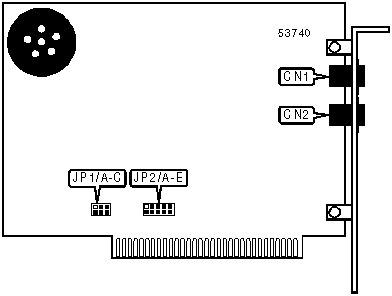
CONNECTIONS | |||
|
Function |
Label |
Function |
Label |
|
Telephone line out |
CN1 |
Telephone line in |
CN2 |
|
USER CONFIGURABLE SETTINGS | ||
|
Setting |
Label |
Position |
|
í Plug-N-Play disabled |
JP1/C |
Closed |
|
Plug-N-Play enabled |
JP1/C |
Open |
|
SERIAL PORT ADDRESS SELECTION | ||
|
Setting |
JP1/A |
JP1/B |
|
3F8h (COM1:) |
Closed |
Closed |
|
í 2E8h (COM2:) |
Open |
Closed |
|
3F8h (COM3:) |
Closed |
Open |
|
2E8h (COM4:) |
Open |
Open |
|
Plug-N-Play |
Open |
Open |
|
INTERRUPT SELECTION | |||||
|
Setting |
JP2/A |
JP2/B |
JP2/C |
JP2/D |
JP2/E |
|
2 |
Closed |
Open |
Open |
Open |
Open |
|
í 3 |
Open |
Closed |
Open |
Open |
Open |
|
4 |
Open |
Open |
Closed |
Open |
Open |
|
5 |
Open |
Open |
Open |
Closed |
Open |
|
7 |
Open |
Open |
Open |
Open |
Closed |
|
Plug-N-Play |
Open |
Open |
Open |
Open |
Open |
|
SUPPORTED STANDARD COMMANDS |
|
Basic AT Commands |
|
+++, ‘comma’, A/ |
|
A, B, D, E, F, H, L, M, O, P, T, V, X, Z |
|
&C, &D, &F, &G, &P, &R, &S, &T, &W |
|
S-Registers |
|
S0, S1, S2, S3, S4, S5, S6, S7, S8, S9, S10, S11, S12, S18, S25, S38 |
Note: See MHI help file for complete information. |
Proprietary AT Command Set
|
BIT-MAPPED REGISTER S13 | ||
|
Format |
AT [cmds] S13=n [cmds] | |
|
Default: |
0 | |
|
Range: |
0 - 223 | |
|
Description: |
Controls DTR reset, DTR dialing, reset dialing, and MNP3. | |
|
Bit |
Value |
Function |
|
0 |
í 01 |
DTR normal. Reset on low DTR. |
|
1 |
í 01 |
Non-error-correcting mode transmit buffer set to 1.5KB. Non-error-correcting mode transmit buffer set to 128 bytes. |
|
2 |
í 01 |
Backspace and delete keys normal. Backspace and delete keys reversed. |
|
3 |
í 01 |
DTR dialing disabled. DTR dialing enabled. |
|
4 |
í 01 |
Reset dialing disabled. Reset dialing enabled. |
|
5 |
0 |
Not used. |
|
6 |
í 01 |
MNP 3 enabled. MNP 3 disabled. |
|
7 |
í 01 |
Modem enters command state when +++ is received. Modem disconnects and enters command state when +++ is received. |
|
BIT-MAPPED REGISTER S15 | |||||
|
Format: |
AT [cmds] S15=n [cmds] | ||||
|
Default: |
0 | ||||
|
Range: |
0 - 511 | ||||
|
Description: |
Controls error correction and compression in selected protocols, MNP modes, and V.42 operation. | ||||
|
Bit |
Value |
Function | |||
|
0 |
í 01 |
Error correction/compression enabled in V.22 mode. Error correction/compression disabled in V.22 mode. | |||
|
1 |
í 01 |
Error correction/compression enabled in V.22bis mode. Error correction/compression disabled in V.22bis mode. | |||
|
2 |
í 01 |
Error correction/compression enabled in V.32 and V.32bis modes. Error correction/compression disabled in V.32 and V.32bis modes. | |||
|
3 |
í 01 |
MNP handshake enabled. MNP handshake disabled. | |||
|
4 |
í 01 |
MNP4 disabled. MNP4 enabled. | |||
|
5 |
í 01 |
MNP3 disabled. MNP3 enabled. | |||
|
6 |
í 01 |
MNP operation normal MNP configured for non-compatible modems. | |||
|
7 |
í 01 |
V.42 enabled. V.42 disabled. | |||
|
8 |
í 01 |
V.42 detection phase enabled. V.42 detection phase disabled. | |||
|
BIT-MAPPED REGISTER S27 | ||
|
Format: |
AT [cmds] S27=n [cmds] | |
|
Default: |
0 | |
|
Range: |
0 - 255 | |
|
Description: |
Controls V.21, V.32 encoding and modulation, V.32bis modulation, V.42 answer tone and selective reject, and 9600 result codes. | |
|
Bit |
Value |
Function |
|
0 |
í 01 |
V.21 disabled. V.21 enabled. |
|
1 |
í 01 |
V.32 trellis coding enabled. V.32 trellis coding disabled. |
|
2 |
í 01 |
V.32 modulation enabled. V.32 modulation disabled. |
|
3 |
í 01 |
2100Hz answer tone enabled. 2100Hz answer tone disabled. |
|
4 |
í 01 |
Fallback to V.23 disabled. Fallback to V.23 enabled. |
|
5 |
í 01 |
V.32bis modulation enabled. V.32bis modulation disabled. |
|
6 |
í 01 |
V.42 selective reject enabled. V.42 selective reject disabled. |
|
7 |
í 01 |
Actual result codes displayed. Force 9600 result codes. |
|
BIT-MAPPED REGISTER S32 | |||||
|
Format: |
AT [cmds] S32=n [cmds] | ||||
|
Default: |
2 | ||||
|
Range: |
0 - 59 | ||||
|
Description: |
Controls V.8 protocol and options, and V.34 and x2 modulation protocols. | ||||
|
Bit |
Value |
Function | |||
|
0 |
í 01 |
V.8 Call Indicate disabled. V.8 Call Indicate enabled. | |||
|
1 |
0 í 1 |
V.8 disabled. V.8 enabled. | |||
|
2 |
0 |
Not used. | |||
|
3 |
í 01 |
V.34 modulation enabled. V.34 modulation disabled. | |||
|
4 |
í 01 |
V.34 modulation at 31.2Kbps and 33.6Kbps enabled. V.34 modulation at 31.2Kbps and 33.6Kbps disabled. | |||
|
5 |
í 01 |
U.S. Robotics x2 modulation enabled. U.S. Robotics x2 modulation disabled. | |||
|
BREAK LENGTH | |
|
Type: |
Register |
|
Format: |
AT [cmds] S21=n [cmds] |
|
Default: |
10 |
|
Range: |
0 - 255 |
|
Unit: |
10 ms |
|
Description: |
Sets the length of error correction mode breaks sent from DCE to DTE. |
|
BREAK TYPE | |
|
Type: |
Configuration |
|
Format: |
AT [cmds] &Yn [cmds] |
|
Description: |
Configures action of break signal. |
|
Command |
Function |
|
&Y0 |
Break empties buffer. |
|
í &Y1 |
Break empties buffer and is sent immediately. |
|
&Y2 |
Break does not empty buffer and is sent immediately. |
|
COMPRESSION MODE | |
|
Type: |
Configuration |
|
Format: |
AT [cmds] &Kn [cmds] |
|
Description: |
Selects the type of data compression that will be used. |
|
Command |
Function |
|
&K0 |
Data compression disabled. |
|
í &K1 |
Auto-detect compression mode. |
|
&K2 |
Data compression enabled. |
|
&K3 |
MNP5 data compression only enabled. |
|
CONNECTION SPEED LOWER LIMIT | |
|
Type: |
Configuration |
|
Format: |
AT [cmds] &Un [cmds] |
|
Description: |
Sets slowest allowed connection speed if &N is set to 1 or higher. |
|
Command |
Function |
|
&U0 |
No minimum connect speed. |
|
&U1 |
Set minimum connect speed to 300bps. |
|
&U2 |
Set minimum connect speed to 1200bps. |
|
&U3 |
Set minimum connect speed to 2400bps. |
|
&U4 |
Set minimum connect speed to 4800bps. |
|
&U5 |
Set minimum connect speed to 7200bps. |
|
&U6 |
Set minimum connect speed to 9600bps. |
|
&U7 |
Set minimum connect speed to 12Kbps. |
|
&U8 |
Set minimum connect speed to 14.4Kbps. |
|
&U9 |
Set minimum connect speed to 16.8Kbps. |
|
&U10 |
Set minimum connect speed to 19.2Kbps. |
|
&U11 |
Set minimum connect speed to 21.6Kbps. |
|
CONNECTION SPEED LOWER LIMIT (CON'T) | |
|
Command |
Function |
|
&U12 |
Set minimum connect speed to 24Kbps. |
|
&U13 |
Set minimum connect speed to 26.4Kbps. |
|
&U14 |
Set minimum connect speed to 28.8Kbps. |
|
&U15 |
Set minimum connect speed to 31.2Kbps. |
|
&U16 |
Set minimum connect speed to 33.6Kbps. |
|
&U17 |
Set minimum connect speed to 33.3Kbps. |
|
&U18 |
Set minimum connect speed to 37.3Kbps. |
|
&U19 |
Set minimum connect speed to 41.3Kbps. |
|
&U20 |
Set minimum connect speed to 42.6Kbps. |
|
&U21 |
Set minimum connect speed to 44Kbps. |
|
&U22 |
Set minimum connect speed to 45.3Kbps. |
|
&U23 |
Set minimum connect speed to 46.6Kbps. |
|
&U24 |
Set minimum connect speed to 48Kbps. |
|
&U25 |
Set minimum connect speed to 49.3Kbps. |
|
&U26 |
Set minimum connect speed to 50.6Kbps. |
|
&U27 |
Set minimum connect speed to 52Kbps. |
|
&U28 |
Set minimum connect speed to 53.3Kbps. |
|
&U29 |
Set minimum connect speed to 54.6Kbps. |
|
&U30 |
Set minimum connect speed to 56Kbps. |
|
&U31 |
Set minimum connect speed to 57.3Kbps. |
|
CONNECTION SPEED UPPER LIMIT | |
|
Type: |
Configuration |
|
Format: |
AT [cmds] &Nn [cmds] |
|
Description: |
Sets required connection speed if &U is set to 0; otherwise, sets fastest allowed connection speed. |
|
Command |
Function |
|
&N0 |
No maximum connect speed. |
|
&N1 |
Set maximum connect speed to 300bps. |
|
&N2 |
Set maximum connect speed to 1200bps. |
|
&N3 |
Set maximum connect speed to 2400bps. |
|
&N4 |
Set maximum connect speed to 4800bps. |
|
&N5 |
Set maximum connect speed to 7200bps. |
|
&N6 |
Set maximum connect speed to 9600bps. |
|
&N7 |
Set maximum connect speed to 12Kbps. |
|
&N8 |
Set maximum connect speed to 14.4Kbps. |
|
&N9 |
Set maximum connect speed to 16.8Kbps. |
|
&N10 |
Set maximum connect speed to 19.2Kbps. |
|
&N11 |
Set maximum connect speed to 21.6Kbps. |
|
&N12 |
Set maximum connect speed to 24Kbps. |
|
&N13 |
Set maximum connect speed to 26.4Kbps. |
|
&N14 |
Set maximum connect speed to 28.8Kbps. |
|
&N15 |
Set maximum connect speed to 31.2Kbps. |
|
CONNECTION SPEED UPPER LIMIT (CON'T) | |
|
Command |
Function |
|
&N16 |
Set maximum connect speed to 33.6Kbps. |
|
&N17 |
Set maximum connect speed to 33.3Kbps. |
|
&N18 |
Set maximum connect speed to 37.3Kbps. |
|
&N19 |
Set maximum connect speed to 41.3Kbps. |
|
&N20 |
Set maximum connect speed to 42.6Kbps. |
|
&N21 |
Set maximum connect speed to 44Kbps. |
|
&N22 |
Set maximum connect speed to 45.3Kbps. |
|
&N23 |
Set maximum connect speed to 46.6Kbps. |
|
&N24 |
Set maximum connect speed to 48Kbps. |
|
&N25 |
Set maximum connect speed to 49.3Kbps. |
|
&N26 |
Set maximum connect speed to 50.6Kbps. |
|
&N27 |
Set maximum connect speed to 52Kbps. |
|
&N28 |
Set maximum connect speed to 53.3Kbps. |
|
&N29 |
Set maximum connect speed to 54.6Kbps. |
|
&N30 |
Set maximum connect speed to 56Kbps. |
|
&N31 |
Set maximum connect speed to 57.3Kbps. |
|
DISPLAY HELP SCREEN - AMPERSAND | |
|
Type: |
Configuration |
|
Format: |
AT [cmds] &$ [cmds] |
|
Description: |
Displays the help screen on the AT& commands. |
|
DISPLAY HELP SCREEN - BASIC | |
|
Type: |
Configuration |
|
Format: |
AT [cmds] $ [cmds] |
|
Description: |
Displays the basic help screen. |
|
DISPLAY HELP SCREEN - DIAL | |
|
Type: |
Configuration |
|
Format: |
AT [cmds] D$ [cmds] |
|
Description: |
Displays the help screen on the dialing commands. |
|
DISPLAY HELP SCREEN - REGISTERS | |
|
Type: |
Configuration |
|
Format: |
AT [cmds] S$ [cmds] |
|
Description: |
Displays the help screen for S registers. |
|
DISPLAY INFORMATION | |
|
Type: |
Immediate |
|
Format: |
AT [cmds] In [cmds] |
|
Description: |
Displays modem properties. |
|
Command |
Function |
|
I0 |
Displays product identification code. |
|
I1 |
Tests and displays ROM checksum result. |
|
I2 |
Tests and displays RAM checksum result. |
|
I4 |
Displays current command settings. |
|
I5 |
Displays current NVRAM settings. |
|
I6 |
Displays current connection’s statistics. |
|
I7 |
Displays product configuration. |
|
DISTINCTIVE RING | |
|
Type: |
Register |
|
Format: |
AT [cmds] S41=n [cmds] |
|
Description: |
Selects whether the modem will use the Distinctive Ring function. |
|
Command |
Function |
|
í S41=0 |
Distinctive ring abled. |
|
S41=1 |
Distinctive ring enabled. |
|
ERROR CORRECTION MODE | |
|
Type: |
Configuration |
|
Format: |
AT [cmds] &Mn [cmds] |
|
Description: |
Selects active error correction protocols. |
|
Command |
Function |
|
&M0 |
Normal mode only. |
|
í &M4 |
Auto-detect mode. |
|
&M5 |
Error correction mode only. |
|
EXTENDED RESULT CODES | |
|
Type: |
Configuration |
|
Format: |
AT [cmds] &An [cmds] |
|
Description: |
Selects extended result codes. |
|
Command |
Function |
|
&A0 |
Extended result codes disabled. |
|
&A1 |
Error correction result codes enabled. |
|
&A2 |
V.32 result code enabled. |
|
í &A3 |
Error correction and compression result codes enabled. |
|
FLOW CONTROL CHARACTER - XOFF | |
|
Type: |
Register |
|
Format: |
AT [cmds] S23=n [cmds] |
|
Default: |
19 |
|
Range: |
0 - 127 |
|
Unit: |
1 ASCII character |
|
Description: |
Sets the character used to represent XOFF. |
|
FLOW CONTROL CHARACTER - XON | |
|
Type: |
Register |
|
Format: |
AT [cmds] S22=n [cmds] |
|
Default: |
17 |
|
Range: |
0 - 127 |
|
Unit: |
1 ASCII character |
|
Description: |
Sets the character used to represent XON. |
|
FLOW CONTROL - MODEM-TO-MODEM | |
|
Type: |
Configuration |
|
Format: |
AT [cmds] &In [cmds] |
|
Description: |
Selects the type of modem-to-modem flow control used. |
|
Command |
Function |
|
í &I0 |
Software flow control disabled. |
|
&I1 |
XON/XOFF pass-through enabled. |
|
&I2 |
XON/XOFF pass-through disabled. |
|
FLOW CONTROL TYPE | |
|
Type: |
Configuration |
|
Format: |
AT [cmds] &Hn [cmds] |
|
Description: |
Sets type of flow control used by modem. |
|
Command |
Function |
|
&H0 |
Flow control disabled. |
|
í &H1 |
CTS/RTS flow control enabled. |
|
&H2 |
XON/XOFF flow control enabled. |
|
&H3 |
CTS/RTS and XON/XOFF flow control enabled. |
|
INACTIVITY TIMER | |
|
Type: |
Register |
|
Format |
AT [cmds] S19=n [cmds] |
|
Default: |
0 |
|
Range: |
0 - 255 |
|
Unit: |
1 minute |
|
Description: |
Maximum duration of DTE and DCE inactivity allowed prior to initiating hang-up process. |
|
LOCK SERIAL PORT | |
|
Type: |
Configuration |
|
Format: |
AT [cmds] &Bn [cmds] |
|
Description: |
Sets operation of serial port speed. |
|
Command |
Function |
|
&B0 |
Serial speed follows connect speed. |
|
&B1 |
Serial speed locked. |
|
í &B2 |
Serial speed locked in error correction mode only. |
|
RESULT CODES | |
|
Type: |
Configuration |
|
Format: |
AT [cmds] Qn [cmds] |
|
Description: |
Enables modem to send result codes to the DTE. |
|
Command |
Function |
|
í Q0 |
Result codes enabled. |
|
Q1 |
Result codes disabled. |
|
Q2 |
Result codes enabled in originate mode only. |
|
TONE DIALING TEST | |
|
Type: |
Register |
|
Format: |
AT [cmds] S16=n [cmds] |
|
Description: |
Begins a tone dialing test. |
|
Command |
Function |
|
í S16=0 |
Tone dialing test disabled. |
|
S16=2 |
Tone dialing test enabled. |
|
V.21 ANSWER MODE FALLBACK TIMER | |
|
Type: |
Register |
|
Format: |
AT [cmds] S29=n [cmds] |
|
Default: |
20 |
|
Range: |
Unidentified |
|
Unit: |
.1 second |
|
Description: |
The function of this register is unidentified. |
|
V.32 HANDSHAKE TIME | |
|
Type: |
Register |
|
Format: |
AT [cmds] S28=n [cmds] |
|
Default: |
8 |
|
Range: |
0 - 255 |
|
Unit: |
.1 second |
|
Description: |
Sets length of V.32 handshake. A value of 255 means that the modem will only accept connections with V.32 at 9600bps. |
|
V.34 MAPPING | ||
|
Type: |
Register | |
|
Format: |
AT [cmds] S34=n [cmds] | |
|
Default: |
0 | |
|
Range: |
0 - 15 | |
|
Description: |
Controls V.34 mapping, non-linear coding, transmit level deviation, pre-emphasis, and pre-coding. | |
|
Bit |
Value |
Function |
|
0 |
í 01 |
8S-2D map enabled. 8S-2D map disabled. |
|
1 |
í 01 |
16S-4D map enabled. 16S-4D map disabled. |
|
2 |
í 01 |
32S-2D map enabled. 32S-2D map disabled. |
|
3 |
í 01 |
64S-4D map enabled. 64S-4D map disabled. |
|
4 |
í 01 |
Non-linear coding enabled. Non-linear coding disabled. |
|
5 |
í 01 |
Transmit level deviation enabled. Transmit level deviation disabled. |
|
6 |
í 01 |
Pre-emphasis enabled. Pre-emphasis disabled. |
|
7 |
í 01 |
Pre-coding enabled. Pre-coding disabled. |
|
V.34 OPTIONS | ||
|
Type: |
Register | |
|
Format: |
AT [cmds] S33=n [cmds] | |
|
Default: |
0 | |
|
Range: |
0 - 255 | |
|
Description: |
Controls V.34 baud rate and shaping. | |
|
Bit |
Value |
Function |
|
0 |
í 01 |
2400 baud rate enabled. 2400 baud rate disabled. |
|
1 |
í 01 |
2743 baud rate enabled. 2743 baud rate disabled. |
|
2 |
í 01 |
2800 baud rate enabled. 2800 baud rate disabled. |
|
3 |
í 01 |
3000 baud rate enabled. 3000 baud rate disabled. |
|
4 |
í 01 |
3200 baud rate enabled. 3200 baud rate disabled. |
|
5 |
í 01 |
3429 baud rate enabled. 3429 baud rate disabled. |
|
6 |
0 |
Not used. |
|
7 |
í 01 |
Shaping enabled. Shaping disabled. |