ACCELERATED COMPUTER TECHNOLOGY, INC.
UNIVERSAL FLOPPY DISK CONTROLLER
|
Card Type |
Floppy drive controller |
|
Chip Set |
Unidentified |
|
Maximum Onboard Memory |
None |
|
I/O Options |
Floppy drive interface (3) |
|
Data Bus |
8-bit ISA |
|
Floppy drives supported |
Four 360KB or 720KB drives Four 360KB, 720KB, 1.2MB, or 1.44MB drives |
|
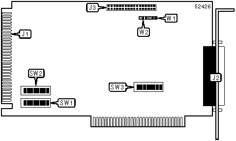
CONNECTIONS | |||
|
Function |
Label |
Function |
Label |
|
34-pin floppy drive interface |
J1 |
34-pin floppy drive interface |
J3 |
|
37-pin floppy drive interface |
J2 | ||
|
Note: J1 is the connector for drives A: and B:, either J2 or J3 can be used to connect drives C: and D:. | |||
|
USER CONFIGURABLE SETTINGS | |||
|
Function |
Label |
Position | |
|
Step rate of floppy drive A is 3 Ms |
SW1/1 |
On | |
|
Step rate of floppy drive A is 6 Ms |
SW1/1 |
Off | |
|
Step rate of floppy drive B is 3 Ms |
SW1/5 |
On | |
|
Step rate of floppy drive B is 6 Ms |
SW1/5 |
Off | |
|
Step rate of floppy drive C is 3 Ms |
SW2/1 |
On | |
|
Step rate of floppy drive C is 6 Ms |
SW2/1 |
Off | |
|
Step rate of floppy drive D is 3 Ms |
SW2/5 |
On | |
|
Step rate of floppy drive D is 6 Ms |
SW2/5 |
Off | |
|
Drive order will be MODE 1(see MISCELLANEOUS TECHNICAL NOTE 2) |
SW3/1 |
Off | |
|
Drive order will be MODE 2 (see MISCELLANEOUS TECHNICAL NOTE 2) |
SW3/1 |
On | |
|
UFDC is the primary floppy drive controller |
SW3/2 |
Off | |
|
UFDC is the secondary floppy drive controller |
SW3/2 |
On | |
| » |
EPROM enabled |
SW3/3 |
On |
|
EPROM disabled |
SW3/3 |
Off | |
| » |
TYPE 1 or 2 drives (see MISCELLANEOUS TECHNICAL NOTE 1) |
W1 |
Pins 1 & 2 closed |
|
TYPE 2 or 3 drives (see MISCELLANEOUS TECHNICAL NOTE 1) |
W1 |
Pins 2 & 3 closed | |
| » |
Pin 2 on the interface cable is an output signal |
W2 |
Pins 1 & 2 closed |
|
Pin 2 on the interface cable is an input signal (TYPE 2 drives only) |
W2 |
Pins 2 & 3 closed | |
|
FLOPPY DRIVE A CONFIGURATION | |||
|
Type |
SW1/2 |
SW1/3 |
SW1/4 |
|
360KB (5.25) |
On |
On |
Off |
|
1.2MB (5.25) |
On |
Off |
On |
|
720KB (3.5) |
On |
Off |
Off |
|
1.44MB (3.5) |
Off |
On |
On |
|
None |
On |
On |
On |
|
FLOPPY DRIVE B CONFIGURATION | |||
|
Type |
SW1/6 |
SW1/7 |
SW1/8 |
|
360KB (5.25) |
On |
On |
Off |
|
1.2MB (5.25) |
On |
Off |
On |
|
720KB (3.5) |
On |
Off |
Off |
|
1.44MB (3.5) |
Off |
On |
On |
|
None |
On |
On |
On |
|
FLOPPY DRIVE C CONFIGURATION | |||
|
Type |
SW2/2 |
SW2/3 |
SW2/4 |
|
360KB (5.25) |
On |
On |
Off |
|
1.2MB (5.25) |
On |
Off |
On |
|
720KB (3.5) |
On |
Off |
Off |
|
1.44MB (3.5) |
Off |
On |
On |
|
None |
On |
On |
On |
|
FLOPPY DRIVE D CONFIGURATION | |||
|
Type |
SW1/6 |
SW1/7 |
SW1/8 |
|
360KB (5.25) |
On |
On |
Off |
|
1.2MB (5.25) |
On |
Off |
On |
|
720KB (3.5) |
On |
Off |
Off |
|
1.44MB (3.5) |
Off |
On |
On |
|
None |
On |
On |
On |
|
EPROM ADDRESS CONFIGURATION | ||||||
|
Address |
SW3/4 |
SW3/5 |
SW3/6 |
SW3/7 |
SW3/8 | |
|
C8000h |
On |
On |
Off |
On |
On | |
| » |
CA000h |
On |
On |
Off |
On |
Off |
|
CC000h |
On |
On |
Off |
Off |
On | |
|
CE000h |
On |
On |
Off |
Off |
Off | |
|
D0000h |
On |
Off |
On |
On |
On | |
|
D2000h |
On |
Off |
On |
On |
Off | |
|
D4000h |
On |
Off |
On |
Off |
On | |
|
D6000h |
On |
Off |
On |
Off |
Off | |
|
EPROM ADDRESS CONFIGURATION (CON’T) | |||||
|
Address |
SW3/4 |
SW3/5 |
SW3/6 |
SW3/7 |
SW3/8 |
|
D8000h |
On |
Off |
Off |
On |
On |
|
DA000h |
On |
Off |
Off |
On |
Off |
|
DC000h |
On |
Off |
Off |
Off |
On |
|
DE000h |
On |
Off |
Off |
Off |
Off |
|
E0000h |
Off |
Off |
On |
On |
On |
|
E2000h |
Off |
Off |
On |
On |
Off |
|
E4000h |
Off |
Off |
On |
Off |
On |
|
E6000h |
Off |
Off |
On |
Off |
Off |
|
E8000h |
Off |
Off |
Off |
On |
On |
|
EA000h |
Off |
Off |
Off |
On |
Off |
|
EC000h |
Off |
Off |
Off |
Off |
On |
|
EE000h |
Off |
Off |
Off |
Off |
Off |
|
MISCELLANEOUS TECHNICAL NOTE |
|
NOTE 1: Due to the tight tolerances in the construction of a 3.5" floppy disk, the write current applied to the heads of the drive needs to be adjusted for either 720KB disks or 1.44MB disks. Floppy disk drive manufactures have used three different mechanisms to modify the write current. They are: TYPE 1:These drives read the current on pin 2 of the interface cable, a 1.44MB disk is assumed for a high current, and a 720KB disk is assumed for a low current. TYPE 2: These drives have a sensor that looks for a cutout in the plastic shell of the disk. If the cutout is present, a 1.44MB disk is assumed. TYPE 3: These drives are found on the IBM PS/2 line of products. They read the current on pin 2 of the interface cable in the opposite manner of TYPE 1’s. That is, a high current signifies a 720KB disk and a low current a 1.44MB disk. NOTE 2: If you have installed more than 2 floppy drives in a system, you have a choice on how the controller treats the third and fourth drives. MODE 1 sets the drives to A:, B:, C:, & D:, in this system your hard drive will be the first available letter. If you have 3 drives installed it will be D:, and if you have all four installed it will be E:. MODE 2 sets your first two floppy drives to A: & B:, and assigns C: to the hard drive. To install additional floppy drives under this system you will need to load a device drive at boot time. |