AMERICAN PREDATOR CORPORATION
PREDATOR LPX
|
Processor |
80486SX/80487SX/80486DX/80486DX2/80486DX4/Pentium Overdrive |
|
Processor Speed |
20/25/33/40/50(internal)/50/66(internal)/75(internal)/83(internal)/ 100(internal)MHz |
|
Chip Set |
OPTI |
|
Max. Onboard DRAM |
64MB |
|
Cache |
128/256KB |
|
BIOS |
AMI |
|
Dimensions |
330mm x 218mm |
|
I/O Options |
32-bit VESA local bus slot, floppy drive interface, IDE interface, parallel port, PS/2 mouse port, serial ports (2), VGA port, ethernet interfaces (2) |
|
NPU Options |
None |
|
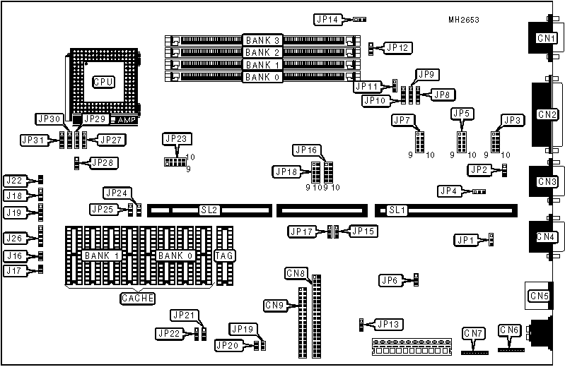
CONNECTIONS | |||
|
Purpose |
Location |
Purpose |
Location |
|
VGA port |
CN1 |
Reset switch |
J16 |
|
Parallel port |
CN2 |
IDE interface LED |
J17 |
|
Serial port 2 |
CN3 |
Turbo LED |
J18 |
|
Serial port 1 |
CN4 |
Speaker |
J19 |
|
PS/2 mouse port |
CN5 |
Ethernet LED |
J21 |
|
Ethernet TP connector |
CN6 |
5v ground |
J22 |
|
Ethernet AUI connector |
CN7 |
Power LED & keylock |
J26 |
|
IDE interface |
CN8 |
Riser Card |
SL1 |
|
Floppy drive interface |
CN9 |
32-bit VESA local bus slot |
SL2 |
|
Note: The location of J21 is unidentified. | |||
|
USER CONFIGURABLE SETTINGS | |||
|
Function |
Jumper |
Position | |
|
» |
Ethernet interface type select twisted pair |
JP1 |
pins 1 & 2 closed |
|
Ethernet interface type select coaxial |
JP1 |
pins 2 & 3 closed | |
|
» |
Mouse IRQ12 enabled |
JP2 |
pins 1 & 2 closed |
|
Mouse IRQ12 disabled |
JP2 |
pins 2 & 3 closed | |
|
» |
Factory configured - do not alter |
JP4 |
N/A |
|
» |
Boot ROM disabled |
JP6 |
pins 1 & 2 closed |
|
Boot ROM enabled |
JP6 |
pins 2 & 3 closed | |
|
» |
Parallel port IRQ select IRQ7 |
JP8 |
pins 1 & 2 closed |
|
Parallel port IRQ select IRQ5 |
JP8 |
pins 2 & 3 closed | |
|
Parallel port IRQ select disabled |
JP8 |
pins 3 & 4 closed | |
|
» |
Serial port 1 IRQ select IRQ4 |
JP9 |
pins 1 & 2 closed |
|
Serial port 1 IRQ select IRQ5 |
JP9 |
pins 2 & 3 closed | |
|
Serial port 1 IRQ select disabled |
JP9 |
pins 3 & 4 closed | |
|
» |
Serial port 2 IRQ select IRQ3 |
JP10 |
pins 1 & 2 closed |
|
Serial port 2 IRQ select IRQ9 |
JP10 |
pins 2 & 3 closed | |
|
Serial port 2 IRQ select disabled |
JP10 |
pins 3 & 4 closed | |
|
» |
On board VGA enabled |
JP11 |
pins 1 & 2 closed |
|
On board VGA disabled |
JP11 |
pins 2 & 3 closed | |
|
» |
VGA IRQ select IRQ9 |
JP12 |
pins 1 & 2 closed |
|
VGA IRQ select disabled |
JP12 |
pins 2 & 3 closed | |
|
» |
On board I/O enabled |
JP13 |
pins 1 & 2 closed |
|
On board I/O disabled |
JP13 |
pins 2 & 3 closed | |
|
» |
CMOS memory normal operation |
JP14 |
pins 1 & 2 closed |
|
CMOS memory clear |
JP14 |
pins 2 & 3 closed | |
|
» |
Factory configured - do not alter |
JP16 |
N/A |
|
» |
Factory configured - do not alter |
JP18 |
N/A |
|
» |
IDE interface enabled |
JP19 |
pins 1 & 2 closed |
|
IDE interface disabled |
JP19 |
pins 2 & 3 closed | |
|
» |
IDE timing select normal |
JP20 |
pins 1 & 2 closed |
|
IDE timing select slow |
JP20 |
pins 2 & 3 closed | |
|
» |
Factory configured - do not alter |
JP24 |
N/A |
|
USER CONFIGURABLE SETTINGS (CON’T) | |||
|
Function |
Jumper |
Position | |
|
» |
IDE wait state select 0 wait states |
JP25 |
pins 1 & 2 closed |
|
IDE wait state select 1 wait state |
JP25 |
pins 2 & 3 closed | |
|
» |
BIOS type select EPROM |
JP28 |
pins 2 & 3 closed |
|
BIOS type select flash |
JP28 |
pins 1 & 2 closed | |
|
» |
Factory configured - do not alter |
JP31 |
N/A |
|
DRAM CONFIGURATION | ||||
|
Size |
Bank 0 |
Bank 1 |
Bank 2 |
Bank 3 |
|
2MB |
(1) 512K x 36 |
NONE |
NONE |
NONE |
|
4MB |
(1) 1M x 36 |
NONE |
NONE |
NONE |
|
6MB |
(1) 512K x 36 |
(1) 1M x 36 |
NONE |
NONE |
|
8MB |
(1) 1M x 36 |
(1) 1M x 36 |
NONE |
NONE |
|
8MB |
(1) 2M x 36 |
NONE |
NONE |
NONE |
|
12MB |
(1) 1M x 36 |
(1) 1M x 36 |
(1) 1M x 36 |
NONE |
|
16MB |
(1) 1M x 36 |
(1) 1M x 36 |
(1) 1M x 36 |
(1) 1M x 36 |
|
16MB |
(1) 4M x 36 |
NONE |
NONE |
NONE |
|
20MB |
(1) 1M x 36 |
(1) 4M x 36 |
NONE |
NONE |
|
24MB |
(1) 1M x 36 |
(1) 1M x 36 |
(1) 4M x 36 |
NONE |
|
28MB |
(1) 1M x 36 |
(1) 1M x 36 |
(1) 4M x 36 |
(1) 1M x 36 |
|
32MB |
(1) 4M x 36 |
(1) 4M x 36 |
NONE |
NONE |
|
32MB |
(1) 8M x 36 |
NONE |
NONE |
NONE |
|
36MB |
(1) 1M x 36 |
(1) 4M x 36 |
(1) 4M x 36 |
NONE |
|
40MB |
(1) 1M x 36 |
(1) 1M x 36 |
(1) 4M x 36 |
(1) 4M x 36 |
|
48MB |
(1) 4M x 36 |
(1) 4M x 36 |
(1) 4M x 36 |
NONE |
|
52MB |
(1) 1M x 36 |
(1) 4M x 36 |
(1) 4M x 36 |
(1) 4M x 36 |
|
64MB |
(1) 4M x 36 |
(1) 4M x 36 |
(1) 4M x 36 |
(1) 4M x 36 |
|
CACHE CONFIGURATION | |||
|
Size |
Bank 0 |
Bank 1 |
TAG |
|
128KB |
(4) 32K x 8 |
NONE |
(1) 8K x 8 |
|
256KB |
(4) 32K x 8 |
(4) 32K x 8 |
(1) 32K x 8 |
|
CACHE JUMPER CONFIGURATION | ||
|
Size |
JP21 |
JP22 |
|
128KB |
pins 1 & 2 closed |
pins 1 & 2 closed |
|
256KB |
pins 2 & 3 closed |
pins 2 & 3 closed |
|
CPU TYPE CONFIGURATION | |||
|
Type |
JP27 |
JP29 |
JP30 |
|
80486SX |
pins 3 & 4 closed |
pins 3 & 4 closed |
pins 3 & 4 closed |
|
80487SX |
pins 2 & 3 closed |
pins 2 & 3 closed |
pins 2 & 3 closed |
|
80486DX |
pins 1 & 2 closed |
pins 1 & 2 closed |
pins 1 & 2 closed |
|
80486DX2 |
pins 1 & 2 closed |
pins 1 & 2 closed |
pins 1 & 2 closed |
|
80486DX4 |
pins 1 & 2 closed |
pins 1 & 2 closed |
pins 1 & 2 closed |
|
Pentium Overdrive |
pins 2 & 3 closed |
pins 2 & 3 closed |
pins 2 & 3 closed |
|
CPU SPEED CONFIGURATION | |
|
Speed |
JP23 |
|
20MHz |
pins 1 & 2 closed |
|
25MHz |
pins 3 & 4 closed |
|
33MHz |
pins 5 & 6 closed |
|
40MHz |
pins 7 & 8 closed |
|
50iMHz |
pins 3 & 4 closed |
|
50MHz |
pins 9 & 10 closed |
|
66iMHz |
pins 5 & 6 closed |
|
75iMHz |
pins 3 & 4 closed |
|
83iMHz |
pins 5 & 6 closed |
|
100iMHz |
pins 5 & 6 closed |
|
IDE MODE CONFIGURATION | ||
|
Mode |
JP15 |
JP17 |
|
0 |
pins 2 & 3 closed |
pins 2 & 3 closed |
|
1 |
pins 2 & 3 closed |
pins 1 & 2 closed |
|
2 |
pins 1 & 2 closed |
pins 2 & 3 closed |
|
3 |
pins 1 & 2 closed |
pins 1 & 2 closed |
|
ETHERNET I/O CONFIGURATION | |
|
I/O address |
JP3 |
|
300h |
pins 3 & 4 closed |
|
320h |
pins 5 & 6 closed |
|
340h |
pins 7 & 8 closed |
|
360h |
pins 9 & 10 closed |
|
Disabled |
pins 1 & 2 closed |
|
ETHERNET DMA CONFIGURATION | |
|
DMA |
JP5 |
|
DMA 3 |
pins 9 & 10 closed |
|
DMA 5 |
pins 3 & 4 closed |
|
DMA 6 |
pins 5 & 6 closed |
|
DMA 7 |
pins 7 & 8 closed |
|
Disabled |
pins 1 & 2 closed |
|
ETHERNET IRQ CONFIGURATION | |
|
IRQ |
JP7 |
|
IRQ3 |
pins 3 & 4 closed |
|
IRQ4 |
pins 5 & 6 closed |
|
IRQ5 |
pins 7 & 8 closed |
|
IRQ9 |
pins 9 & 10 closed |
|
Disabled |
pins 1 & 2 closed |