AMPRO COMPUTERS, INC.
LITTLE BOARD/P5I
|
Processor |
Pentium |
|
Processor Speed |
100/133/166MHz |
|
Chip Set |
Unidentified |
|
Video Chip Set |
Unidentified |
|
Maximum Onboard Memory |
128MB (EDO supported) |
|
Maximum Video Memory |
1MB |
|
Cache |
256KB |
|
BIOS |
Award |
|
Dimensions |
203mm x 146mm |
|
I/O Options |
PCI bus slot, Ethernet 10BaseT connector, AUI connector, floppy drive interface, IDE interface, SCSI interface, parallel port, serial ports (4), VGA interface, VEE power supply, flat panel connector, external video overlay, PC/104 connectors (2) |
|
NPU Options |
None |
|
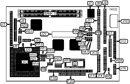
CONNECTIONS | |||
|
Purpose |
Location |
Purpose |
Location |
|
Flat panel connector |
J3 |
IDE interface |
J12 |
|
VEE power supply |
J4 |
Serial port 3 & 4 |
J13 |
|
VGA interface |
J5 |
Floppy drive interface |
J14 |
|
External video overlay |
J6 |
Parallel port |
J15 |
|
Ethernet 10BaseT connector |
J7 |
Utility/keyboard connector |
J16 |
|
AUI connector |
J8 |
IDE extension |
J17 |
|
SCSI-interface |
J9 |
PCI bus slot |
J21 |
|
DC power |
J10 |
PC/104 connector |
P18 |
|
Serial port 1 & 2 |
J11 |
PC/104 connector |
P20 |
|
Note: Alternate external LAN media are , such as 10Base2 are available by means of AUI interface & optional MAUs. | |||
|
USER CONFIGURABLE SETTINGS | |||
|
Function |
Label |
Position | |
|
» |
Factory configured - do not alter |
J20 |
Unidentified |
|
Negative vee enabled |
W1 |
Pins 1 & 2 closed | |
|
Negative vee disabled |
W1 |
Pins 2 & 3 closed | |
|
» |
Factory configured - do not alter |
W8 |
Unidentified |
|
» |
Factory configured - do not alter |
W9 |
Unidentified |
|
» |
Factory configured - do not alter |
W10 |
Unidentified |
|
» |
Factory configured - do not alter |
W11 |
Unidentified |
|
» |
Factory configured - do not alter |
W12 |
Unidentified |
|
» |
Factory configured - do not alter |
W13 |
Unidentified |
|
» |
Factory configured - do not alter |
W14 |
Unidentified |
|
» |
Factory configured - do not alter |
W16 |
Unidentified |
|
SCSI interface enabled |
W17 |
Pins 1 & 2 closed | |
|
SCSI interface disabled |
W17 |
Pins 2 & 3 closed | |
|
» |
Factory configured - do not alter |
W20 |
Unidentified |
|
» |
Factory configured - do not alter |
W22 |
Unidentified |
|
» |
Data valid select high to low transition |
W23 |
Pins 1 & 2 closed |
|
Data valid select low to high transition |
W23 |
Pins 2 & 3 closed | |
|
Watch dog timer select IOCHK |
W24 |
Pins 1 & 2 closed | |
|
Watch dog timer select RESET |
W24 |
Pins 2 & 3 closed | |
|
Watch dog timer disabled |
W24 |
Open | |
|
DRAM CONFIGURATION | |
|
Size |
Bank 0 |
|
8MB |
(2) 1M x 36 |
|
16MB |
(2) 2M x 36 |
|
32MB |
(2) 4M x 36 |
|
64MB |
(2) 8M x 36 |
|
128MB |
(2) 16M x 36 |
|
Note: Board accepts EDO memory. Board also accepts x 32 SIMMs. | |
|
CACHE CONFIGURATION |
|
Note: The location of the 256KB cache is unidentified. |
|
VIDEO MEMORY CONFIGURATION |
|
Note: The location of the 512KB/1MB video memory is unidentified. |
|
DMA CHANNEL SELECTION | ||
|
Channel |
W18 |
W19 |
|
1 |
Pins 1 & 2 closed |
Pins 1 & 2 closed |
|
3 |
Pins 2 & 3 closed |
Pins 2 & 3 closed |
|
SERIAL PORT 1 INTERRUPT SELECTION | ||
|
IRQ |
W4 |
W6 |
|
IRQ4 shared with serial 1 |
Pins 1 & 2 closed |
Open |
|
IRQ4 not shared |
Pins 2 & 3 closed |
Closed |
|
SERIAL PORT 2 INTERRUPT SELECTION | ||
|
IRQ |
W5 |
W7 |
|
IRQ3 shared with serial 2 |
Pins 1 & 2 closed |
Open |
|
IRQ3 not shared |
Pins 2 & 3 closed |
Closed |
|
BIOS SELECTION (EPROM) | |||
|
Type |
W2 |
W15 |
W21 |
|
27C64 |
Open |
2 & 5, 7 & 8, 9 & 12, 10 & 11 |
1 & 2 |
|
27C128 |
Open |
2 & 5, 7 & 8, 9 & 12, 10 & 11 |
1 & 2 |
|
27C256 |
Open |
9 & 12, 14 & 15 |
1 & 2 |
|
27C512 |
Open |
9 & 12, 10 & 11, 14 & 15 |
1 & 2 |
|
27C010 |
Open |
2 & 5, 7 & 8, 9 & 12, 10 & 11 |
1 & 2 |
|
27C020 |
Open |
2 & 5, 7 & 8, 9 & 12, 10 & 11, 13 & 14 |
1 & 2 |
|
27C040 |
Open |
2 & 5, 4 & 7, 9 & 12, 10 & 11, 13 & 14 |
1 & 2 |
|
27C080 |
Open |
4 & 7, 5 & 6, 9 & 12, 10 & 11, 13 & 14 |
1 & 2 |
|
28C64 |
Open |
2 & 5, 7 & 8, 9 & 12, 10 & 11 |
1 & 2 |
|
Note: Pins designated should be in the closed position. | |||
|
BIOS SELECTION (FLASH BIOS) | |||
|
Type |
W2 |
W15 |
W21 |
|
29C256 |
Open |
8 & 11, 9 & 12, 14 & 15 |
1 & 2 |
|
28C256 |
Open |
8 & 9, 11 & 12, 14 & 15 |
1 & 2 |
|
29F512 |
Open |
4 & 5, 7 & 8, 9 & 12, 10 & 11, 13 & 14 |
1 & 2 |
|
29F010 |
Open |
4 & 5, 7 & 8, 9 & 12, 10 & 11, 13 & 14 |
1 & 2 |
|
29F020 |
Open |
4 & 5, 7 & 8, 9 & 12, 10 & 11, 13 & 14 |
1 & 2 |
|
29F040 |
Open |
4 & 5, 7 & 8, 9 & 12, 10 & 11, 13 & 14 |
1 & 2 |
|
28F512 |
Open |
2 & 5, 7 & 8, 9 & 12, 10 & 11, 13 & 14 |
1 & 2 |
|
28F010 |
Open |
2 & 5, 7 & 8, 9 & 12, 10 & 11, 13 & 14 |
1 & 2 |
|
28F020 |
Open |
2 & 5, 7 & 8, 9 & 12, 10 & 11, 13 & 14 |
1 & 2 |
|
Note: Pins designated should be in the closed position. | |||
|
BIOS SELECTION (SRAM & NOVRAM) | |||
|
Type |
W2 |
W15 |
W21 |
|
BQ4013Y |
Closed |
7 & 10, 8 & 9, 11 & 12, 14 & 15 |
2 & 3 |
|
BQ4015Y |
Closed |
4 & 5, 7 & 10, 8 & 9, 11 & 12, 13 & 14 |
2 & 3 |
|
43256 |
Closed |
7 & 10, 8 & 9, 11 & 12, 14 & 15 |
2 & 3 |
|
DS1235Y |
Closed |
7 & 10, 8 & 9, 11 & 12, 14 & 15 |
2 & 3 |
|
DS1650Y |
Closed |
4 & 5, 7 & 10, 8 & 9, 11 & 12, 13 & 14 |
2 & 3 |
|
628128 |
Closed |
7 & 10, 8 & 9, 11 & 12, 14 & 15 |
2 & 3 |
|
628512 |
Closed |
4 & 5, 7 & 10, 8 & 9, 11 & 12, 13 & 14 |
2 & 3 |
|
Note: Pins designated should be in the closed position. | |||