ACER AMERICA CORPORATION
MODEM 2424
|
Modem Type |
Data (synchronous/asynchronous) |
|
Maximum Data Rate |
2400bps |
|
Data Bus |
External |
|
Data Modulation Protocol |
Bell 103A/212A, 201 ITU-T V.22, V.22bis |
|
Error Correction/Compression |
MNP4 |
|
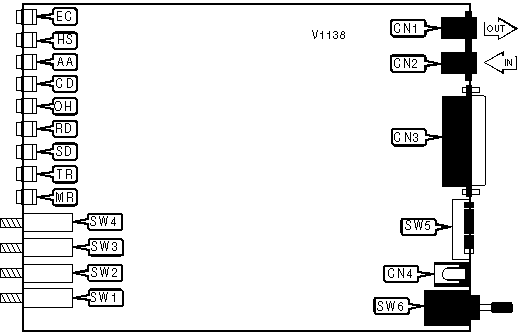
CONNECTIONS | |||
|
Purpose |
Location |
Purpose |
Location |
|
Line out |
CN1 |
DC power |
CN4 |
|
Line in |
CN2 |
Power switch |
SW6 |
|
RS-232C |
CN3 | ||
|
OFF HOOK | |
|
Status |
SW4 |
| » Talk mode |
Off |
| Data mode |
On |
|
ANSWER MODE | |
|
Status |
SW3 |
| » Originate |
Off |
| Answer |
On |
|
MODEM SPEED | |
|
Speed |
SW2 |
| » 2400bps |
Off |
| 1200bps |
On |
|
AUTO TEST | |
|
Status |
SW1 |
| » Disabled |
Off |
| Enabled |
On |
|
COMMAND SET DISABLE | |
|
Status |
SW5/1 |
|
AT command set disabled |
On |
|
AT command set enabled |
Off |
|
LINE TYPE | |
|
Status |
SW5/2 |
|
Force leased line |
On |
|
Normal operation |
Off |
|
ERROR CORRECTION | |
|
Status |
SW5/3 |
|
Disabled |
On |
|
Enabled |
Off |
|
ECHO AND RESULT CODE | |
|
Status |
SW5/4 |
|
Disabled |
On |
|
Normal operation |
Off |
|
AUTO ANSWER | |
|
Status |
SW5/5 |
|
Set to one ring |
On |
|
Normal operation |
Off |
|
SYNCHRONOUS TRANSMIT CLOCK SOURCE | |
|
Status |
SW5/6 |
|
DTE generates clock |
On |
|
Normal operation |
Off |
|
SYNCRONOUS DATA MODE | |
|
Status |
SW5/7 |
|
Enabled |
On |
|
Normal operation |
Off |
|
DSR AND CTS | |
|
Status |
SW5/8 |
|
Force high |
On |
|
Normal operation |
Off |
|
DIAGNOSTIC LED(S) | ||
|
LED |
Status |
Condition |
|
EF |
On |
Error correction enabled |
|
EF |
Off |
Error correction disabled |
|
HS |
On |
Modem is operating at 2400bps |
|
HS |
Off |
Modem is operating at 1200bps or 300bps |
|
AA |
On |
Auto answer enabled |
|
AA |
Off |
Auto answer disabled |
|
CD |
On |
Carrier signal detected |
|
CD |
Off |
Carrier signal not detected |
|
OH |
On |
Modem is off-hook |
|
OH |
Off |
Modem is on-hook |
|
RD |
On |
Modem is receiving data |
|
RD |
Off |
Modem is not receiving data |
|
SD |
On |
Modem is transmitting data |
|
SD |
Off |
Modem is not transmitting data |
|
TR |
On |
DTR signal is high |
|
TR |
Off |
DTR signal is low |
|
MR |
On |
Power on |
|
MR |
Off |
Power off |
|
MR |
Blinking |
Modem is performing self-test |
Proprietary AT Command Set
|
ACCEPT RELIABLE MODE | |
|
Type: |
Immediate |
|
Format: |
AT [cmds] \Un |
|
Example: |
AT \U <CR> |
|
Description: |
Accepts remote modem’s request for reliable link. |
|
AUTO-RELIABLE TIME BUFFER CONFIGURATION | |
|
Type: |
Configuration |
|
Format: |
AT [cmds] \Cn [cmds] |
|
Example: |
AT \C1 &W <CR> |
|
Description: |
Controls the handling of incoming data during auto-reliable time period. |
| Command |
Function |
| » \C0 |
Data is discarded. |
| \C1 |
Data is buffered. |
|
AUTO-RELIABLE FALLBACK CHARACTER | |
|
Type: |
Register |
|
Format: |
AT [cmds] S20=n [cmds] |
|
Example: |
ATS20=20 <CR> |
|
Default: |
0 |
|
Range: |
0-127 |
|
Unit: |
ASCII |
|
Description: |
Sets the character used as the auto-reliable fallback character. S20=0 will disable this function. |
|
AUTO-RETRAIN | |
|
Type: |
Configuration |
|
Format: |
AT %En |
|
Example: |
AT %E1 <CR> |
|
Description: |
Selects auto-retrain mode. |
| Command |
Function |
| » %E0 |
Auto-retrain disabled. |
| %E1 |
Auto-retrain enabled. |
|
BIT MAPPED REGISTER S14 | |||
|
Format |
AT [cmds] S14=n [cmds] | ||
|
Example: |
ATS14=40 <CR> | ||
|
Default: |
170 | ||
|
Range: |
0 - 253 | ||
|
Unit: |
Bit-mapped | ||
|
Description: |
Controls CTS signal, command echo, result codes, command set, dialing mode, and answer/originate mode. | ||
|
Bit | Value |
Function | |
|
0 | » 0 1 |
CTS normal. CTS forced high. | |
|
1 | 0 » 1 |
Command echo disabled. Command echo enabled. | |
|
2 | » 0 1 |
Result codes enabled. Result codes disabled. | |
|
3 | 0 » 1 |
Display numeric result codes. Display verbose result codes. | |
|
4 | » 0 1 |
AT command set enabled. AT command set disabled | |
|
5 | 0 » 1 |
Tone dialing enabled. Pulse dialing enabled. | |
|
6 | 0 |
Not used | |
|
7 | 0 » 1 |
Answer mode enabled. Originate mode enabled. | |
|
BIT-MAPPED REGISTER S21 | |||
|
Format |
AT [cmds] S21=n [cmds] | ||
|
Example: |
ATS21=4 <CR> | ||
|
Default: |
32 | ||
|
Range: |
0 - 253 | ||
|
Unit: |
Bit-mapped | ||
|
Description: |
Selects jack type, CTS signal, low DTR action, DCD signal, DSR signal, and the Long Space Disconnect function. | ||
|
Bit | Value |
Function | |
|
0 | » 0 1 |
Selects RJ-11, RJ-41S, or RJ45S jack. Selects RJ-12 or RJ-13 jack. | |
|
1 | 0 |
Not used. | |
|
2 | 0 » 1 |
CTS follows RTS. CTS forced high. | |
|
4, 3 | » 00 01 10 11 |
DTR signal ignored. Modem goes to command mode on low DTR. Modem disconnects on low DTR. Auto-Answer is disabled. Modem is initialized on low DTR. | |
|
5 | 0 » 1 |
DCD forced high. DCD normal. | |
|
6 | 0 |
Not used. | |
|
7 | » 0 1 |
Long Space Disconnect function disabled. Long Space Disconnect function enabled. | |
|
BIT-MAPPED REGISTER S22 | |||
|
Format |
AT [cmds] S22=n [cmds] | ||
|
Example: |
ATS22=117 <CR> | ||
|
Default: |
117 | ||
|
Range: |
0-127 | ||
|
Unit: |
Bit-mapped | ||
|
Description: |
Controls speaker volume and controls, and limits results codes. | ||
|
Bit | Value |
Function | |
|
1, 0 | 00 » 01 10 11 |
Off volume. On volume. Medium level volume. High level volume. | |
|
3, 2 | 00 » 01 10 11 |
Speaker off. Speaker off on carrier. Speaker always on. Speaker on during handshake. | |
|
6, 5, 4 | 000 100 101 110 » 111 |
Basic result codes only enabled. Basic and connection speed result codes enabled. Basic and connection speed result codes and dialtone detection enabled. All result codes except dialtone detection enabled. All result codes enabled. | |
|
7 | » 0 1 |
39/61ms at 10pps (North America) 33/67ms at 10pps (Europe) | |
|
BIT-MAPPED REGISTER S23 | |||
|
Format |
AT [cmds] S23=n [cmds] | ||
|
Example: |
ATS23=177 <CR> | ||
|
Default: |
5 | ||
|
Range: |
0-255 | ||
|
Unit: |
Bit-mapped | ||
|
Description: |
Grants/denies remote digital loopback, controls DTE rate and parity, and sets guard tone. | ||
|
Bit | Value |
Function | |
|
0 | 0 » 1 |
Remote digital loopback denied. Remote digital loopback allowed. | |
|
3, 2, 1 | 000 001 » 010 011 100 101 110 |
Sets serial port speed to 0-300bps. Sets serial port speed to 600bps. Sets serial port speed to 1200bps. Sets serial port speed to 2400bps. Sets serial port speed to 4800bps. Sets serial port speed to 9600bps. Sets serial port speed to 19200bps. | |
|
5,4 | » 00 01 10 11 |
Even parity. Space parity. Odd parity. Mark or no parity. | |
|
7, 6 | » 00 01 10 |
Guard tone disabled. Guard tone disabled. Guard tone 1800Hz enabled. | |
|
BIT-MAPPED REGISTER S27 | |||
|
Format |
AT [cmds] S27=n [cmds] | ||
|
Example: |
ATS27=192 <CR> | ||
|
Default: |
9 | ||
|
Range: |
0 - 127 | ||
|
Unit: |
Bit-mapped | ||
|
Description: |
Selects sync/async mode, line type, clock source, and ITU-T/Bell modes. | ||
|
Bit | Value |
Function | |
|
1, 0 | 00 01 » 10 11 |
Asynchronous command and data modes. Asynchronous command, synchronous connect mode. DTR dialing enabled, synchronous connect mode. Manual dialing only, synchronous connect mode. | |
|
2 | » 0 1 |
Switched line. Leased line. | |
|
3 | 0 |
Not used. | |
|
5, 4 | » 00 01 10 |
Internal DTE transmit clock source. External DTE transmit clock source. Slave DTE transmit clock source. | |
|
6 | » 0 1 |
ITU-T mode enabled. Bell mode disabled. | |
|
BREAK SEND | |
|
Type: |
Configuration |
|
Format: |
AT [cmds] \Bn [cmds] |
|
Example: |
AT \B3 &W <CR> |
|
Range: |
1-9 |
|
Unit: |
.1 second |
|
Description: |
Sends break to modem. |
|
BREAK TYPE | |||||
|
Type: |
Configuration | ||||
|
Format: |
AT [cmds] \Kn [cmds] | ||||
|
Example: |
AT \K1 <CR> | ||||
|
Description: |
Configures action of break signal. | ||||
|
Command |
Break from DTE Reliable/Normal mode |
Break from DTE Direct mode |
Modem receives \B |
Break from remote modem | |
| \K0 |
Enter command mode, do not send break to remote modem. |
Send break to remote modem immediately, then enter command mode. |
Buffers cleared and break sent to remote modem. |
Buffers cleared and break sent to DTE. | |
| \K1 |
Buffers cleared and break sent to remote modem. |
Send break to remote modem immediately. |
Buffers cleared and break sent to remote modem. |
Buffers cleared and break sent to DTE. | |
| \K2 |
Enter command mode, do not send break to remote modem. |
Send break to remote modem immediately, then enter command mode. |
Send break to remote modem immediately. |
Send break to DTE immediately. | |
| \K3 |
Send break to remote modem immediately. |
Send break to remote modem immediately. |
Send break to remote modem immediately. |
Send break to DTE immediately. | |
| \K4 |
Enter command mode, do not send break to remote modem. |
Send break to remote modem immediately, then enter command mode. |
Send break to remote modem with transmitted data. |
Break sent with received data to the DTE. | |
| » \K5 |
Send break with transmitted data. |
Send break to remote modem immediately. |
Send break to remote modem with transmitted data. |
Break sent with received data to the DTE. | |
|
CHANGE FUNCTION | |
|
Type: |
Configuration |
|
Format: |
AT [cmds] %Z <cmds> |
|
Example: |
AT %Z DP(303)443-3388 <CR> |
|
Description: |
Changes the function of SW1 to execute the commands given as a parameter. If no commands are given, it restores default setting of self-test. |
|
CONNECT MODE | |
|
Type: |
Configuration |
|
Format: |
AT [cmds] \Nn [cmds] |
|
Example: |
AT \N1 DT555-1212 <CR> |
|
Description: |
Sets connect mode. |
|
Command |
Function |
| \N0 |
Normal mode. |
| » \N1 |
Direct mode. |
| \N2 |
Reliable mode. |
| \N3 |
Auto-reliable mode. |
|
CONNECTION SPEED UPPER LIMIT | |
|
Type: |
Configuration |
|
Format: |
AT [cmds] %Bn [cmds] |
|
Example: |
AT %L3 %B14 \J0<CR> |
|
Description: |
Sets fastest allowed connection speed. |
| Command |
Function |
| %B300 |
Select 300bps maximum speed. |
| %B600 |
Select 600bps maximum speed. |
| %B1200 |
Select 1200bps maximum speed. |
| » %B2400 |
Select 2400bps maximum speed. |
|
CONVERT TO RELIABLE MODE | |
|
Type: |
Immediate |
|
Format: |
AT [cmds] \Y [cmds] |
|
Example: |
AT \Y <CR> |
|
Description: |
Initiates reliable mode link. |
|
CTS SIGNAL | |
|
Type: |
Configuration |
|
Format: |
AT [cmds] \Dn [cmds] |
|
Example: |
AT \D0 <CR> |
|
Description: |
Controls action of Clear To Send signal. |
| Command |
Function |
| » \D0 |
CTS forced high. |
| \D1 |
CTS normal. |
|
DIAL | |
|
Type: |
Immediate |
|
Format: |
AT [cmds] D[phone# & modifiers] [;cmds] |
|
Example: |
AT H1 DF 9W *70, 1(303) 555-1212 <CR> |
|
Description: |
Dials telephone number according to any modifiers included in the string. |
|
Note: |
Any combination of modifiers can be used to produce the desired dial functions in sequence. |
| Command |
Function |
|
DF |
Fast pulse dial, sends 20 pulses per second. |
|
DX |
Dial second stored telephone number |
|
D\n |
Auto redial n times |
|
DM |
Set AT\N3, AT\V1, AT\Q1, AT\J0 until modem returns to on-hook. |
|
DISPLAY STORED PHONE NUMBERS | |
|
Type: |
Immediate |
|
Format: |
AT [cmds] \F [cmds] |
|
Example: |
AT &Z2=9W1-303-555-1212 \F <CR> |
|
Description: |
Displays all stored phone numbers. |
|
ECHO DATA | |
|
Type: |
Configuration |
|
Format: |
AT [cmds] \En [cmds] |
|
Example: |
AT \E0 <CR> |
|
Description: |
Displays data sent from DTR to modem |
| Command |
Function |
| » \E0 |
Disabled |
| \E1 |
Enabled |
|
EXTENDED RESULT CODES | |
|
Type: |
Configuration |
|
Format: |
AT [cmds] \Vn [cmds] |
|
Example: |
AT \V1 %C1 <CR> |
|
Description: |
Selects MNP result codes. |
| Command |
Function |
| » \V0 |
MNP result codes disabled. |
| \V1 |
MNP result codes enabled. |
|
FLOW CONTROL TYPE | |
|
Type: |
Configuration |
|
Format: |
AT [cmds] \Qn [cmds] |
|
Example: |
AT \Q5 <CR> |
|
Description: |
Sets type of flow control used by modem. |
| Command |
Function |
| \Q0 |
Flow control disabled. |
| » \Q1 |
Bidirectional XON/XOFF flow control enabled. |
| \Q2 |
CTS flow control by DCE enabled. |
| \Q3 |
Bidirectional CTS/RTS flow control enabled. |
| \Q4 |
Flow control by DCE disabled. |
| » \Q5 |
XON/XOFF flow control by DCE enabled. |
| \Q6 |
RTS flow control by DCE enabled. |
|
HELP SCREENS | |
|
Type: |
Immediate |
|
Format: |
AT [cmds] ?n [cmds] |
|
Example: |
AT ?1 <CR> |
|
Description: |
Displays help menus. |
| Command |
Function |
| » ?1 |
Displays standard AT command set |
| ?2 |
Displays proprietary & command set |
| ?3 |
Displays dial modifier commands |
| ?4 |
Displays S register contents. |
| ?5 |
Displays proprietary \ command set |
|
INACTIVITY TIMER | |
|
Type: |
Register |
|
Format: |
AT [cmds] S24=n [cmds] |
|
Example: |
ATS24=20 <CR> |
|
Default: |
0 |
|
Range: |
0-90 |
|
Unit: |
1 minute |
|
Description: |
Sets the length of time that the modem does not receive information before it disconnects. |
|
INACTIVITY TIMER | |
|
Type: |
Register |
|
Format: |
AT [cmds] \Tn [cmds] |
|
Example: |
AT\T20 <CR> |
|
Default: |
0 |
|
Range: |
0-255 |
|
Unit: |
1 second |
|
Description: |
Sets the length of time that the modem does not receive information before it disconnects. |
|
INTERFACE PROTOCOL | |
|
Type: |
Configuration |
|
Format: |
AT [cmds] \In [cmds] |
|
Example: |
AT \I0 <CR> |
|
Description: |
Controls data exchange between applications and modem. |
| Command |
Function |
| » \I0 |
Disabled. |
| \I1 |
Enabled. |
|
FLOW CONTROL | |
|
Type: |
Configuration |
|
Format: |
AT [cmds] \Gn [cmds] |
|
Example: |
AT G1 &M0 <CR> |
|
Description: |
Selects modem port flow control. |
| Command |
Function |
| » \G0 |
Flow control disabled. |
| \G1 |
Flow control enabled. |
|
LOCK SERIAL PORT | |
|
Type: |
Configuration |
|
Format: |
AT [cmds] \Jn [cmds] |
|
Example: |
AT %L3 %B14 \J0<CR> |
|
Description: |
Sets operation of serial port speed. |
| Command |
Function |
| \J0 |
Serial speed locked. |
| » \J1 |
Serial speed follows connect speed. |
|
MAXIMUM BLOCK SIZE FOR TRANSMISSION | |
|
Type: |
Configuration |
|
Format: |
AT [cmds] \An [cmds] |
|
Example: |
AT \A3 %C1 <CR> |
|
Description: |
Sets the maximum transmittable block size. |
|
Command |
Function |
|
\A0 |
MNP block size is 64 characters. |
|
\A1 |
MNP block size is 128 characters. |
|
\A2 |
MNP block size is 192 characters. |
|
\A3 |
MNP block size is 256 characters. |
|
MNP STREAM/BLOCK MODE | |
|
Type: |
Configuration |
|
Format: |
AT [cmds] \Ln [cmds] |
|
Example: |
AT \L1 DT555-1212 <CR> |
|
Description: |
Selects the transfer mode for MNP. |
| Command |
Function |
| » \L0 |
Stream mode for MNP enabled. |
| \L1 |
Block mode after four second delayfor MNP enabled. |
| \L2 |
Block mode for MNP enabled. |
|
ON-LINE IN RELIABLE MODE | |
|
Type: |
Immediate |
|
Format: |
AT [cmds] \On |
|
Example: |
AT \O <CR> |
|
Description: |
Returns to on-line and requests reliable mode connection. |
|
REPORT CONFIGURATION PROFILES | |
|
Type: |
Immediate |
|
Format: |
AT [cmds] \Sn [cmds] |
|
Example: |
AT \S0 <CR> |
|
Description: |
Reports active configuration profiles. |
|
REPORT CONFIGURATION SWITCH SETTINGS | |
|
Type: |
Immediate |
|
Format: |
AT [cmds] %S [cmds] |
|
Example: |
AT %S <CR> |
|
Description: |
Displays SW5 settings |
|
REPORT NORMAL/TEST STATUS | |
|
Type: |
Immediate |
|
Format: |
AT [cmds] %F [cmds] |
|
Example: |
AT %F <CR> |
|
Description: |
Displays current setting of SW1 (Normal/Test) |
|
REPORT PRODUCT VERSION | |
|
Type: |
Immediate |
|
Format: |
AT [cmds] %V [cmds] |
|
Example: |
AT I3 &V1 %V <CR> |
|
Description: |
Reports product version. |
|
RETURN TO RELIABLE MODE | |
|
Type: |
Immediate |
|
Format: |
AT [cmds] \Z [cmds] |
|
Example: |
AT \Z <CR> |
|
Description: |
Ends reliable mode link, initiate return to normal mode. |
|
RI SIGNAL | |
|
Type: |
Configuration |
|
Format: |
AT [cmds] \Rn [cmds] |
|
Example: |
AT \R0 Q0 <CR> |
|
Description: |
Controls the behavior of the Ring Indicator signal. |
| Command |
Function |
| \R0 |
RI signal high during rings, and forced high for duration of call. |
| » \R1 |
RI signal high during rings only. |
|
STORE SECOND PHONE NUMBER IN NVRAM | |
|
Type: |
Configuration |
|
Format: |
AT [cmds] \Pn [dialstring] |
|
Example: |
AT\P <CR> |
|
Description: |
Stores a second phone number in the modem’s memory. |
|
REDIAL DELAY | |
|
Type: |
Register |
|
Format: |
AT [cmds] S19=n [cmds] |
|
Example: |
AT S19=60 <CR> |
|
Default: |
45 |
|
Range: |
0-255 |
|
Unit: |
1 second |
|
Description: |
Configures how long the modem will wait to redial a number after a dial attempt has failed. |
|
TEST MODES | |||
|
Format |
AT [cmds] S16=n [cmds] | ||
|
Example: |
ATS16=40 <CR> | ||
|
Default: |
0 | ||
|
Range: |
0-125 | ||
|
Unit: |
Bit-mapped | ||
|
Description: |
Controls loopback tests, analog, digital, remote digital, and self tests. | ||
|
Bit |
Value |
Function | |
|
0 |
0 1 |
Local analog loopback not in progress. Local analog loopback in progress. | |
|
1 |
0 |
Not used. | |
|
2 |
0 1 |
Local digital loopback not in progress. Local digital loopback in progress. | |
|
3 |
0 1 |
Remote digital loopback not in progress. Remote digital loopback in progress. | |
|
4 |
0 1 |
Remote digital loopback not requested. Remote digital loopback requested. | |
|
5 |
0 1 |
Remote digital loopback with self-test not in progress. Remote digital loopback with self-test in progress. | |
|
6 |
0 1 |
Local analog loopback with self-test not in progress. Local analog loopback with self-test in progress. | |
|
XON/XOFF PASS-THROUGH | |
|
Type: |
Configuration |
|
Format: |
AT [cmds] \Xn [cmds] |
|
Example: |
AT \X0 O <CR> |
|
Description: |
Selects whether XON/XOFF signals are sent to remote modem. |
| Command |
Function |
| » \X0 |
XON/XOFF signals trapped by local modem. |
| \X1 |
XON/XOFF passed through local modem. |