ELSA, INC.
MICROLINK 33.6TQV
|
Card Type |
Modem (asynchronous) |
|
Chipset |
Unidentified |
|
I/O Options |
Voice |
|
Maximum Data Rate |
33.6Kbps |
|
Maximum Fax Rate |
14.4Kbps |
|
Data Modulation |
Bell 103A, 212A ITU-T V.21, V.22, V.23, V.32, V.32bis, V.34 Rockwell V.FC |
|
Fax Modulation |
ITU-T V.17, V.27ter, V.29, V.33 |
|
Error Correction/Compression |
MNP5, V.42, V.42bis |
|
Fax Class |
Class I & II |
|
Data Bus |
Serial |
|
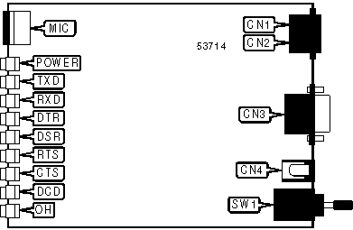
CONNECTIONS | |||
|
Function |
Label |
Function |
Label |
|
Telephone line in |
CN1 |
DC power in |
CN4 |
|
Telephone line out |
CN2 |
Power switch |
SW1 |
|
Serial port |
CN3 | ||
|
DIAGNOSTIC LED(S) | |||
|
LED |
Color |
Status |
Condition |
|
POWER |
Red |
On |
Power is on |
|
POWER |
Red |
Off |
Power is off |
|
TXD |
Red |
On |
Modem is transmitting data |
|
TXD |
Red |
Off |
Modem is not transmitting data |
|
RXD |
Red |
On |
Modem is receiving data |
|
RXD |
Red |
Off |
Modem is not receiving data |
|
DTR |
Red |
On |
DTR signal is high |
|
DTR |
Red |
Off |
DTR signal is low |
|
DSR |
Red |
On |
DSR signal is high |
|
DSR |
Red |
Off |
DSR signal is low |
|
RTS |
Red |
On |
RTS signal is high |
|
RTS |
Red |
Off |
RTS signal is low |
|
DIAGNOSTIC LED(S) (CON'T) | |||
|
LED |
Color |
Status |
Condition |
|
CTS |
Red |
On |
CTS signal is high |
|
CTS |
Red |
Off |
CTS signal is low |
|
DCD |
Red |
On |
Carrier signal detected |
|
DCD |
Red |
Off |
Carrier signal not detected |
|
OH |
Red |
On |
Modem is off-hook |
|
OH |
Red |
Off |
Modem is on-hook |
|
SUPPORTED STANDARD COMMANDS |
|
Basic AT Commands |
|
+++, ‘comma’, A/ |
|
A, B, E, H, L, M, O, P, T, V, X, Z |
|
&D, &F, &S, &T, &V, &W, &Y, &Z |
|
Extended AT Commands |
|
\C, \J, \K, \N, \Q, \T, \X |
|
%A, %C, %E |
|
Special AT Commands |
|
-J |
|
S-Registers |
|
S0, S1, S2, S3, S4, S5, S6, S7, S8, S9, S10, S11, S12, S16, S21, S22, S25, S26, S30, S38 |
Note: See MHI help file for complete information. |
Proprietary AT Command Set
|
AUTO-RELIABLE FALLBACK CHARACTER | |
|
Type: |
Register |
|
Format: |
AT [cmds] S47=n [cmds] |
|
Default: |
13 |
|
Range: |
0-127 |
|
Unit: |
1 ASCII character |
|
Description: |
Sets the character used as the auto-reliable fallback character; S47=0 will disable this function. |
|
BIT-MAPPED REGISTER S14 | ||
|
Format: |
AT [cmds] S14=n [cmds] | |
|
Default: |
81 | |
|
Range: |
0 - 254 | |
|
Description: |
Controls echo, result codes and display, dial mode, and answer/originate mode. | |
|
Bit |
Value |
Function |
|
0 |
í 0 |
Not used. |
|
1 |
0 í 1 |
Command echo disabled. Command echo enabled. |
|
2 |
í 01 |
Result codes enabled. Result codes disabled. |
|
3 |
0 í 1 |
Display result codes in numeric format. Display result codes in verbose format. |
|
4 |
í 01 |
Command set enabled. Command set disabled. (See -H command for more information.) |
|
5 |
í 01 |
Tone dial enabled. Pulse dial enabled. |
|
6 |
í 01 |
Polling not allowed during connection establishment. Polling allowed during connection establishment. |
|
7 |
0 í 1 |
Answer mode enabled. Originate mode enabled. |
|
BIT-MAPPED REGISTER S27 | |||||
|
Format: |
AT [cmds] S27=n [cmds] | ||||
|
Default: |
0 | ||||
|
Range: |
0 - 192 | ||||
|
Description: |
Controls modulation protocol and duplexing. | ||||
|
Bit |
Value |
Function | |||
|
5 - 0 |
000000 |
Not used. | |||
|
6 |
í 01 |
ITU/T mode. Bell mode. | |||
|
7 |
í 01 |
Full-duplex mode. Half-duplex mode. | |||
|
BIT-MAPPED REGISTER S28 | |||||
|
Format: |
AT [cmds] S28=n [cmds] | ||||
|
Default: |
6 | ||||
|
Range: |
0 - 239 | ||||
|
Description: |
Controls low DTR control, automatic retrain, bit rate tolerance, V.100 fallback, and data format. | ||||
|
Bit |
Value |
Function | |||
|
1, 0 |
00 01 í 1011 |
Modem set for 8 data bits in direct mode. Modem set for 9 data bits in direct mode. Modem set for 10 data bits in direct mode. Modem set for 11 data bits in direct mode. | |||
|
3, 2 |
00 í 0110 11 |
Non-V.100 fallback enabled. V.100 fallback enabled. Fallback disabled. V.100 fallback enabled. | |||
|
4 |
0 |
Not used. | |||
|
5 |
í 01 |
Bit rate tolerance set to between -2.5% and +1%. Bit rate tolerance set to between -2.5% and +2.3%. | |||
|
6 |
í 01 |
Automatic retrain enabled. Automatic retrain disabled. | |||
|
7 |
í 01 |
Modem will not accept calls and generate RING response when DTR is low. Modem will accept calls and generate RING response when DTR is low. | |||
|
BIT-MAPPED REGISTER S29 | |||||
|
Format: |
AT [cmds] S29=n [cmds] | ||||
|
Default: |
66 | ||||
|
Range: |
0 - 247 | ||||
|
Description: |
Controls V.FC ID for V.8, trellis coding, V.32 clear down sequence, V.34 and V.FC rate re-negotiation, V.8 adaptation, asymmetric bit rates, and fallback to V.23. | ||||
|
Bit |
Value |
Function | |||
|
0 |
í 01 |
Fallback to V.23 enabled. Fallback to V.23 disabled. | |||
|
1 |
0 í 1 |
Asymmetric bit rates disabled. Asymmetric bit rates enabled. | |||
|
2 |
í 01 |
V.8 adaptation enabled. V.8 adaptation disabled. | |||
|
3 |
0 |
Not used. | |||
|
4 |
í 01 |
V.34 and V.FC rate re-negotiation enabled. V.34 and V.FC rate re-negotiation disabled. | |||
|
5 |
í 01 |
V.32 clear down sequence disabled. V.32 clear down sequence enabled. | |||
|
6 |
0 í 1 |
Trellis coding in V.32 disabled. Trellis coding in V.32 enabled. | |||
|
7 |
í 01 |
V.8 answer tone includes V.FC identification. V.8 answer tone does not include V.FC identification. | |||
|
BIT-MAPPED REGISTER S31 | |||||
|
Format: |
AT [cmds] S31=n [cmds] | ||||
|
Default: |
0 | ||||
|
Range: |
0 - 63 | ||||
|
Description: |
Controls guard tone, calling tone, manual dialing DTR connection, and DTR dialing. | ||||
|
Bit |
Value |
Function | |||
|
1, 0 |
í 0001 10 |
Guard tone disabled. 550Hz guard tone enabled. 1800Hz guard tone enabled. | |||
|
2 |
í 01 |
Calling tone enabled. Calling tone disabled. | |||
|
3 |
í 01 |
V.25 calling tone enabled. V.8 calling tone enabled. | |||
|
4 |
í 01 |
Modem will not attempt to connect on high DTR. Modem will attempt to connect on high DTR. | |||
|
5 |
í 01 |
DTR dialing disabled. DTR dialing enabled. | |||
|
BIT-MAPPED REGISTER S33 | |||||
|
Format: |
AT [cmds] S33=n [cmds] | ||||
|
Default: |
0 | ||||
|
Range: |
0 - 14 | ||||
|
Description: |
Controls callback mode, callback trace, and remote configuration. | ||||
|
Bit |
Value |
Function | |||
|
0, 1 |
í 0001 10 |
Callback disabled. Callback enabled; RING and CONNECT are displayed before login prompts. Callback enabled; RING and CONNECT are displayed after login prompts. | |||
|
2 |
í 01 |
Callback trace disabled. Callback trace enabled. | |||
|
3 |
í 01 |
Remote configuration disabled. Remote configuration enabled. | |||
|
BIT-MAPPED REGISTER S36 | |||||
|
Format: |
AT [cmds] S36=n [cmds] | ||||
|
Default: |
131 | ||||
|
Range: |
0 - 134 | ||||
|
Description: |
Controls connect mode and Selective Reject. | ||||
|
Bit |
Value |
Function | |||
|
2 - 0 |
000 001 010 í 011100 101 110 |
Normal mode enabled. Direct mode enabled. MNP reliable mode enabled. Auto-reliable mode enabled. V.42 reliable mode enabled. V.42 auto-reliable mode enabled. V.42 or MNP reliable mode enabled. | |||
|
6 - 3 |
0000 |
Not used. | |||
|
7 |
í 01 |
Selective Reject enabled. Selective Reject disabled. | |||
|
BIT-MAPPED REGISTER S37 | |||||
|
Format: |
AT [cmds] S37=n [cmds] | ||||
|
Default: |
19 | ||||
|
Range: |
0 - 211 | ||||
|
Description: |
Controls line, modem, and serial port speed options. | ||||
|
Bit |
Value |
Function | |||
|
4 - 0 |
00001 00010 00011 00101 00110 00111 01000 01001 01010 01011 01100 01101 01110 01111 10000 10001 10010 í 10011 |
Set line speed to 75/1200bps. Set line speed to 1200/75bps. Set line speed to 300bps. Set line speed to 1200bps. Set line speed to 2400bps. Set line speed to 4800bps. Set line speed to 7200bps. Set line speed to 9600bps. Set line speed to 12Kbps. Set line speed to 14.4Kbps. Set line speed to 16.8Kbps. Set line speed to 19.2Kbps. Set line speed to 21.6Kbps. Set line speed to 24Kbps. Set line speed to 26.4Kbps. Set line speed to 28.8Kbps. Set line speed to 31.2Kbps. Set line speed to 33.6Kbps. | |||
|
5 |
0 |
Not used. | |||
|
6 |
í 01 |
Modem port speed changed automatically. User must change modem port speed with %B command. | |||
|
7 |
í 01 |
Serial port speed follows connect speed. Serial port speed locked. | |||
|
BIT-MAPPED REGISTER S48 | |||||
|
Format: |
AT [cmds] S48=n [cmds] | ||||
|
Default: |
164 | ||||
|
Range: |
0 - 180 | ||||
|
Description: |
Controls V.42 detection phase, auto-reliable time buffer, and break type. | ||||
|
Bit |
Value |
Function | |||
|
1 - 0 |
00 |
Not used. | |||
|
2 |
0 í 1 |
V.42 detection phase disabled. V.42 detection phase enabled. | |||
|
4, 3 |
í 0001 10 |
Data is discarded during auto-reliable time. Data is buffered for 4 seconds or 200 characters during auto-reliable time. Data is discarded during auto-reliable time; modem returns to normal mode on receiving auto-reliable fallback character. | |||
|
7 - 5 |
000 001 010 011 100 í 101 |
\K0 is selected. \K1 is selected. \K2 is selected. \K3 is selected. \K4 is selected. \K5 is selected. | |||
|
BIT-MAPPED REGISTER S87 | |||
|
Format: |
AT [cmds] S87? [cmds] | ||
|
Default: |
Read-only | ||
|
Range: |
0 - 211 | ||
|
Description: |
Returns a value indicating current transmit line speed, fax mode connection, and modulation protocol type. | ||
|
Bit |
Value |
Meaning | |
|
4 - 0 |
00001 00010 00011 00101 00110 00111 01000 01001 01010 01011 01100 01101 01110 01111 10000 10001 10010 10011 |
Transmit line speed is 75/1200bps. Transmit line speed is 1200/75bps. Transmit line speed is 300bps. Transmit line speed is 1200bps. Transmit line speed is 2400bps. Transmit line speed is 4800bps. Transmit line speed is 7200bps. Transmit line speed is 9600bps. Transmit line speed is 12Kbps. Transmit line speed is 14.4Kbps. Transmit line speed is 16.8Kbps. Transmit line speed is 19.2Kbps. Transmit line speed is 21.6Kbps. Transmit line speed is 24Kbps. Transmit line speed is 26.4Kbps. Transmit line speed is 28.8Kbps. Transmit line speed is 31.2Kbps. Transmit line speed is 33.6Kbps. | |
|
BIT-MAPPED REGISTER S87 (CON'T) | ||||
|
Bit |
Value |
Meaning | ||
|
5 |
0 |
Not used. | ||
|
6 |
0 1 |
Modem is not connected in fax mode. Modem is connected in fax mode. | ||
|
7 |
0 1 |
ITU-T protocols selected. Bell protocols selected. | ||
|
BIT-MAPPED REGISTER S88 | |||||
|
Format: |
AT [cmds] S88? [cmds] | ||||
|
Default: |
Read-only | ||||
|
Range: | |||||
|
Description: |
Returns a value indicating | ||||
|
Bit |
Value |
Meaning | |||
|
0 |
0 1 |
Modem is not connected with MNP1 through MNP4. Modem is connected with MNP1 through MNP4. | |||
|
1 |
0 1 |
Modem is not connected with MNP5. Modem is connected with MNP5. | |||
|
2 |
0 1 |
Modem is not connected with V.42. Modem is connected with V.42. | |||
|
3 |
0 1 |
Modem is not connected with V.42bis. Modem is connected with V.42bis. | |||
|
BIT-MAPPED REGISTER S89 | |||
|
Format: |
AT [cmds] S89? [cmds] | ||
|
Default: |
Read-only | ||
|
Range: |
0 - 211 | ||
|
Description: |
Returns a value indicating current receive line speed and modulation protocol. | ||
|
Bit |
Value |
Meaning | |
|
4 - 0 |
00001 00010 00011 00101 00110 00111 01000 01001 01010 01011 01100 01101 01110 01111 10000 10001 10010 10011 |
Receive line speed is 75/1200bps. Receive line speed is 1200/75bps. Receive line speed is 300bps. Receive line speed is 1200bps. Receive line speed is 2400bps. Receive line speed is 4800bps. Receive line speed is 7200bps. Receive line speed is 9600bps. Receive line speed is 12Kbps. Receive line speed is 14.4Kbps. Receive line speed is 16.8Kbps. Receive line speed is 19.2Kbps. Receive line speed is 21.6Kbps. Receive line speed is 24Kbps. Receive line speed is 26.4Kbps. Receive line speed is 28.8Kbps. Receive line speed is 31.2Kbps. Receive line speed is 33.6Kbps. | |
|
BIT-MAPPED REGISTER S89 (CON'T) | ||||
|
Bit |
Value |
Meaning | ||
|
7 - 5 |
000 001 010 011 100 101 110 111 |
Modulation protocol in use is V.23. Modulation protocol in use is V.21. Modulation protocol in use is V.22bis. Modulation protocol in use is V.32. Modulation protocol in use is V.32bis. Modulation protocol in use is V.FC. Modulation protocol in use is V.34. Modulation protocol in use is V.34 with asymmetric bit rates. | ||
|
BIT-MAPPED REGISTER S95 | |||||
|
Format: |
AT [cmds] S95=n [cmds] | ||||
|
Default: |
8 | ||||
|
Range: |
0 - 184 | ||||
|
Description: |
Controls result code options and CONNECT response after invalid escape sequence. | ||||
|
Bit |
Value |
Function | |||
|
3 - 0 |
0000 0001 0010 í 1000 |
Extended result codes disabled. /REL extended result codes enabled. LAPM and MNP extended result codes enabled. V.42bis, MNP5, and modulation protocol (if selected with S96) extended result codes enabled. | |||
|
4 |
í 01 |
Modem uses \V command to select extended result codes. Modem always displays extended result codes. | |||
|
5 |
í 01 |
Modem will send CONNECT response after invalid escape sequence. Modem will not send CONNECT response after invalid escape sequence. | |||
|
7, 6 |
í 0001 10 |
Result codes enabled. Result codes disabled. Result codes disabled in answer mode. | |||
|
BIT-MAPPED REGISTER S96 | |||||
|
Format: |
AT [cmds] S96=n [cmds] | ||||
|
Default: |
8 | ||||
|
Range: |
0 - 110 | ||||
|
Description: |
Controls register display, end-of-page prompting, modem language, bit rate display, and \V8 result code format. | ||||
|
Bit |
Value |
Function | |||
|
1, 0 |
í 0001 10 |
Modem will display register values in decimal. Modem will display register values in hexadecimal. Modem will display register values in binary. | |||
|
2 |
í 01 |
Modem will prompt user to press a key after a full page of text. Modem will not prompt user to press a key after a full page of text. | |||
|
3 |
0 í 1 |
Modem text displayed in German. Modem text displayed in English. | |||
|
4 |
0 |
Not used. | |||
|
5 |
í 01 |
Modem will display transmit bit rate. Modem will display both transmit and receive bit rate. | |||
|
6 |
í 01 |
Modem will display only error correction and compression result codes with \V8. Modem will display error correction, compression, and modulation result codes with \V8. | |||
|
BIT-MAPPED REGISTER S130 | |||||
|
Format: |
AT [cmds] S130=n [cmds] | ||||
|
Default: |
4 | ||||
|
Range: |
0 - 220 | ||||
|
Description: |
Controls T.4 bit order, fax mode, fill bit removal, fax mode flow control, and V.17 modulation. | ||||
|
Bit |
Value |
Function | |||
|
1, 0 |
00 |
Not used. | |||
|
2 |
0 í 1 |
T.4 bit order for Class 2 fax receive reversed. T.4 bit order for Class 2 fax receive normal. | |||
|
3 |
í 01 |
Modem is in normal fax mode. Modem is in Elsa TransFax mode. | |||
|
4 |
í 01 |
Fill bits are removed from T.4 data. Fill bits are not removed from T.4 data. | |||
|
5 |
0 |
Not used. | |||
|
6 |
í 01 |
Unidirectional CTS and XON/XOFF flow control enabled. Flow control set by \Q command. | |||
|
7 |
í 01 |
V.17 fax modulation enabled. V.17 fax modulation disabled. | |||
|
CALL FAILURE INDICATION | |
|
Type: |
Register (read-only) |
|
Format: |
AT [cmds] S86? [cmds] |
|
Description: |
Returns a value indicating the cause of the last disconnect. |
|
Value |
Meaning |
|
0 |
Normal disconnection, no error occurred. |
|
4 |
Loss of carrier occurred. |
|
5 |
Negotiation phase failed; modem at remote station has no error correction. |
|
6 |
Remote modem is not answering protocol requests. |
|
7 |
Remote modem is only functioning synchronously. |
|
8 |
Modems could not find a common framing scheme. |
|
9 |
Modems could not find a common protocol. |
|
10 |
Remote modem is sending incorrect protocol requests. |
|
11 |
Synchronous information is missing; connection terminated after 30 seconds. |
|
12 |
Normal disconnect initiated by the remote modem. |
|
13 |
Remote modem is no longer answering; connection terminated after 10 re-transmissions. |
|
14 |
Protocol violation occurred. |
|
15 |
Compression error occurred. |
|
16 |
Inactivity timer has elapsed. |
|
17 |
No loop current detected. |
|
20 |
Busy tone detected. |
|
21 |
No dial tone detected. |
|
22 |
No answer tone detected. |
|
23 |
No connection reached, connection timed out, or wrong modulation type. |
|
24 |
Fallback not permitted because of AT%L2; connection terminated. |
|
25 |
No modem or fax is answering at the number called. |
|
30 |
ATH was entered online. |
|
31 |
ATZ was entered online. |
|
32 |
AT&T0 was entered - modem is in analog loopback test. |
|
33 |
Keystroke received during handshaking. |
|
34 |
DTR signal dropped. |
|
60 |
V.32/V32bis handshake signal AA, CC, AC or CA missing. |
|
61 |
V.32/V.32bis handshake signal R1, R2 or R3 missing. |
|
62 |
V.32/V.32bis handshake signal S missing. |
|
63 |
V.32/V.32bis handshake signal transition from S to \S missing. |
|
64 |
V.32/V.32bis handshake signal E missing. |
|
68 |
No answer to automatic retrain. |
|
CALLBACK | |
|
Type: |
Configuration |
|
Format: |
AT [cmds] $Bn [cmds] |
|
Description: |
Selects what type of callback procedure is used. |
|
Command |
Function |
|
í $B0 |
Callback disabled. |
|
$B1 |
Callback enabled; RING and CONNECT result codes are displayed before login prompts. |
|
$B2 |
Callback enabled; RING and CONNECT result codes are displayed after login prompts. |
|
CALLBACK DELAY | |
|
Type: |
Register |
|
Format: |
AT [cmds] S43=n [cmds] |
|
Default: |
1 |
|
Range: |
0 - 2 |
|
Unit: |
1 minute |
|
Description: |
Sets the amount of time that must elapse before the modem will attempt a callback sequence. |
|
CALLBACK - MAXIMUM CALLBACK ATTEMPTS | |
|
Type: |
Register |
|
Format: |
AT [cmds] S35=n [cmds] |
|
Default: |
3 |
|
Range: |
1 - 99 |
|
Unit: |
1 callback |
|
Description: |
Sets the maximum number of callback attempts the modem will perform. |
|
CALLBACK TRACE | |
|
Type: |
Configuration |
|
Format: |
AT [cmds] $Tn [cmds] |
|
Description: |
Selects whether the progress of callback procedures will be displayed as a diagnostic tool. |
|
Command |
Function |
|
í $T0 |
Callback trace disabled. |
|
$T1 |
Callback trace enabled. |
|
COMMAND SET | |
|
Type: |
Configuration |
|
Format: |
AT [cmds] -Hn [cmds] |
|
Description: |
Selects whether the modem will generate result codes and accept commands. When the command set is disabled, the modem will still accept the -H and D commands, and will act as if S0=1. |
|
Command |
Function |
|
í -H0 |
Command set enabled. |
|
-H1 |
Command set disabled. |
|
COMPRESSION | |
|
Type: |
Register |
|
Format: |
AT [cmds] S46=n [cmds] |
|
Description: |
Selects data compression. |
|
Command |
Function |
|
S46=0 |
Data compression disabled. |
|
S46=1 |
MNP5 enabled. |
|
S46=2 |
V.42bis enabled. |
|
í S46=3 |
MNP5 and V.42bis enabled. |
|
CTS, DCD, AND DSR SIGNALS | |||||
|
Format: |
AT [cmds] S52=n [cmds] | ||||
|
Default: |
4 | ||||
|
Range: |
0 - 11 | ||||
|
Description: |
Controls the behaviour of the CTS, DCD, and DSR signals. | ||||
|
Bit |
Value |
Function | |||
|
0 |
í 01 |
DSR forced high. DSR normal. | |||
|
1 |
í 01 |
CTS forced high. CTS normal. | |||
|
3, 2 |
00 í 0110 |
DCD forced high. DCD forced high after carrier signal is detected. DCD forced high except at disconnect. | |||
|
DATA FORMAT | |
|
Type: |
Register |
|
Format: |
AT [cmds] S53=n [cmds] |
|
Description: |
Controls the data length, parity, and stop bit for the local serial port. |
|
Command |
Function |
|
í S53=0 |
Data format set to 8N1, 7E1, 7O1, or 7N2. |
|
S53=1 |
Data format set to 8E1 |
|
S53=2 |
Data format set to 8O1 |
|
S53=3 |
Data format set to 8N2 |
|
DCD SIGNAL | |
|
Type: |
Configuration |
|
Format: |
AT [cmds] &Cn [cmds] |
|
Description: |
Controls the behaviour of the DCD signal. |
|
Command |
Function |
|
í &C0 |
DCD forced high. |
|
&C1 |
DCD forced high after carrier signal is detected. |
|
&C2 |
DCD forced high except at disconnect. |
|
DIAL | |
|
Type: |
Immediate |
|
Format: |
AT [cmds] D <#> [cmds] |
|
Description: |
Dials the telephone number indicated according to any modifiers included in the string. |
|
Command |
Function |
|
DL |
Re-dial last number. |
|
DM |
Make a LAPM reliable mode connection this call. |
|
DP |
Pulse dialing enabled. |
|
DQ |
Make an LAPM auto-reliable mode connection this call. |
|
DSn |
Dial stored telephone number n. |
|
DT |
Tone dialing enabled. |
|
DV |
Make an LAPM or MNP reliable mode connection this call. |
|
DW |
Dialing resumed following dial tone detection. |
|
DX |
Make an auto-reliable mode connection this call. |
|
DY |
Make an MNP reliable mode connection this call. |
|
DZ |
Make a normal mode connection this call. |
|
D, |
Dialing paused for amount of time specified in S8 register. |
|
D< |
Dialing paused for 1 second. |
|
D/n |
Dial stored telephone number n. |
|
D! |
Flash function initiated. Modem commanded to go off-hook for specified time before returning on-hook. |
|
D@ |
Wait for Quiet Answer function enabled. Modem waits until a "quiet answer," a ring-back signal followed by silence up to the time specified in S7, is received prior to executing the rest of the dial string. |
|
D& |
Flash function initiated. Modem commanded to go off-hook for specified time before returning on-hook. |
|
D= |
Dialing paused for 3 seconds. |
|
D[ |
Flash function initiated. Modem commanded to go off-hook for specified time before returning on-hook. |
|
D; |
Modem returned to idle state after dialing. The semicolon can only be placed at the end of the dial command. |
|
D: |
Dialing resumed following dial tone detection. |
|
DISCONNECT BUFFER DELAY | |
|
Type: |
Configuration |
|
Format |
AT [cmds] %Dn [cmds] |
|
Default: |
0 |
|
Range: |
0-255 |
|
Unit: |
1 second |
|
Description: |
Sets maximum duration allowed during buffered data calls for modem to perform clearing functions after losing carrier-signal or receiving a clear call signal from the remote modem and before initiating hang-up process. |
|
DISPLAY CONFIGURATION | ||
|
Type: |
Immediate | |
|
Format: |
AT [cmds] \Sn [cmds] | |
|
Description: |
Displays the settings of all commands. | |
|
Command |
Function | |
|
\S0 |
Displays all command settings. | |
|
\S1 |
Displays all command settings. | |
|
\S2 |
Displays line and host interface, protocol, and result code/speaker command settings. | |
|
\S3 |
Displays host interface, protocol, and result code/speaker command settings. | |
|
\S4 |
Displays host interface and result code/speaker command settings. | |
|
\S5 |
Displays result code/speaker command settings. | |
|
DISPLAY FIRMWARE VERSION | |
|
Type: |
Immediate |
|
Format: |
AT [cmds] %V [cmds] |
|
Description: |
Displays the current firmware version. |
|
DISPLAY INFORMATION | |
|
Type: |
Immediate |
|
Format: |
AT [cmds] In [cmds] |
|
Description: |
Displays information requested about the modem. |
|
Command |
Function |
|
I0 |
Displays product identification code. |
|
I1 |
Displays ROM checksum. |
|
I2 |
Tests and displays ROM checksum result. |
|
I3 |
Displays firmware revision. |
|
I4 |
Displays configuration. |
|
I5 |
Displays serial number. |
|
I6 |
Displays product name. |
|
I7 |
Displays result of power-up self-test. |
|
I9 |
Displays Plug-N-Play information. |
|
DISPLAY REGISTERS | |
|
Type: |
Immediate |
|
Format: |
AT [cmds] %R [cmds] |
|
Description: |
Displays all status registers. |
|
DISPLAY STORED NUMBERS | |
|
Type: |
Immediate |
|
Format: |
AT [cmds] \F [cmds] |
|
Description: |
Displays all stored telephone numbers. |
|
DSR AND CTS SIGNALS | |
|
Type: |
Configuration |
|
Format: |
AT [cmds] \Dn [cmds] |
|
Description: |
Controls the behaviour of the DSR and CTS signals. |
|
Command |
Function |
|
í \D0 |
DSR and CTS forced high. |
|
\D1 |
DSR normal, CTS forced high. |
|
\D2 |
DSR forced high, CTS follow CD. |
|
\D3 |
DSR normal, CTS forced high. |
|
DTR DIALING | |
|
Type: |
Configuration |
|
Format: |
AT [cmds] $Dn [cmds] |
|
Description: |
Selects whether the modem will use DTR dialing. |
|
Command |
Function |
|
í $D0 |
DTR dialing disabled. |
|
$D1 |
DTR dialing enabled. |
|
EXTENDED RESULT CODE SELECTION | |
|
Type: |
Configuration |
|
Format: |
AT [cmds] -Mn [cmds] |
|
Description: |
Selects whether the modem will use the \V command to select extended result codes. |
|
Command |
Function |
|
í -M0 |
Modem uses \V command to select extended result codes. |
|
-M1 |
Modem always displays extended result codes. |
|
EXTENDED RESULT CODES | |
|
Type: |
Configuration |
|
Format: |
AT [cmds] \Vn [cmds] |
|
Description: |
Selects extended result codes. |
|
Command |
Function |
|
\V0 |
Extended result codes disabled. |
|
\V1 |
/REL extended result codes enabled. |
|
\V2 |
LAPM and MNP extended result codes enabled. |
|
í \V8 |
V.42bis, MNP5, and modulation protocol (if selected with S96) extended result codes enabled. |
|
FLOW CONTROL OPTIONS | |||||
|
Format: |
AT [cmds] S51=n [cmds] | ||||
|
Default: |
3 | ||||
|
Range: |
0 - 20 | ||||
|
Description: |
Controls flow control type and XON/XOFF pass-through. | ||||
|
Bit |
Value |
Function | |||
|
2 - 0 |
000 001 010 í 011100 |
Flow control disabled. Bidirectional XON/XOFF flow control enabled. CTS flow control by DCE enabled. Bidirectional RTS/CTS flow control enabled. Unidirectional XON/XOFF flow control by DCE enabled. | |||
|
3 |
0 |
Not used. | |||
|
4 |
í 01 |
XON/XOFF signals trapped by local modem. XON/XOFF signals passed through by local modem. | |||
|
GUARD TONE AND CALLING TONE | |
|
Type: |
Configuration |
|
Format: |
AT [cmds] &Gn [cmds] |
|
Description: |
Commands the modem to transmit a calling tone, and a guard tone in V.22 or V.22bis modes. |
|
Command |
Function |
|
í &G0 |
Guard tone disabled, calling tone enabled. |
|
&G1 |
550Hz guard tone and calling tone enabled. |
|
&G2 |
1800Hz guard tone and calling tone enabled. |
|
&G4 |
Guard and calling tones disabled. |
|
&G5 |
550Hz guard tone enabled, calling tone disabled. |
|
&G6 |
1800Hz guard tone enabled, calling tone disabled. |
|
INVALID ESCAPE SEQUENCE RESULT CODE | |
|
Type: |
Configuration |
|
Format: |
AT [cmds] *Qn [cmds] |
|
Description: |
Selects whether the modem will send a CONNECT response when an invalid escape sequence has been entered. |
|
Command |
Function |
|
í *Q0 |
Modem will send CONNECT response. |
|
*Q1 |
Modem will not send CONNECT response. |
|
LINE SPEED | |
|
Type: |
Configuration |
|
Format: |
AT [cmds] %Bnnnn [cmds] |
|
Description: |
Sets the speed that the modem will attempt to connect at. |
|
Command |
Function |
|
%B300 |
Set speed to 300bps. |
|
%B1200 |
Set speed to 1200bps. |
|
%B1200/75 |
Set speed to 1200/75bps. |
|
%B75/1200 |
Set speed to 75/1200bps. |
|
%B2400 |
Set speed to 2400bps. |
|
%B4800 |
Set speed to 4800bps. |
|
%B7200 |
Set speed to 7200bps. |
|
%B9600 |
Set speed to 9600bps. |
|
%B12000 |
Set speed to 12Kbps. |
|
%B14400 |
Set speed to 14.4Kbps. |
|
%B16800 |
Set speed to 16.8Kbps. |
|
%B19200 |
Set speed to 19.2Kbps. |
|
%B21600 |
Set speed to 21.6Kbps. |
|
%B24000 |
Set speed to 24Kbps. |
|
%B26400 |
Set speed to 26.4Kbps. |
|
%B28800 |
Set speed to 28.8Kbps. |
|
%B31200 |
Set speed to 31.2Kbps. |
|
%B33600 |
Set speed to 33.6Kbps. |
|
LOCAL SERIAL PORT SPEED - CURRENT | |||||
|
Format: |
AT [cmds] S93? [cmds] | ||||
|
Default: |
Read-only | ||||
|
Range: |
0 - 16 | ||||
|
Description: |
Returns a value indicating the current local serial port speed. | ||||
|
Bit |
Value |
Meaning | |||
|
4 - 0 |
00000 00001 00010 00011 00100 00101 00110 00111 01000 01001 01010 01011 01100 01101 01110 10000 |
DTE rate 300 bps DTE rate 300 bps DTE rate 300 bps DTE rate 300 bps DTE rate 600 bps DTE rate 1200 bps DTE rate 2400 bps DTE rate 4800 bps DTE rate 7200 bps DTE rate 9600 bps DTE rate 12,000 bps DTE rate 14,400 bps DTE rate 19,200 bps DTE rate 38,400 bps DTE rate 57,600 bps DTE rate 115,200 bps | |||
|
LOCAL SERIAL PORT SPEED MATCHING | ||
|
Type: |
Configuration | |
|
Format: |
AT [cmds] %Gn [cmds] | |
|
Description: |
Selects whether the speed of the modem’s port will be changed to match the local serial port, or if the user must do it by hand. | |
|
Command |
Function | |
|
í %G0 |
Speed changed automatically. | |
|
%G1 |
User must change speed with %B command. | |
|
MANUAL DIALING DTR CHANGE | |
|
Type: |
Configuration |
|
Format: |
AT [cmds] :Dn [cmds] |
|
Description: |
Selects whether the modem will attempt to connect to a manually dialed call when DTR goes high. |
|
Command |
Function |
|
í :D0 |
Modem will not attempt to connect on high DTR. |
|
:D1 |
Modem will attempt to connect on high DTR. |
|
RECEIVED SIGNAL LEVEL | |
|
Type: |
Register |
|
Format: |
AT [cmds] 65? [cmds] |
|
Default: |
Read-only |
|
Range: |
0 - 43 |
|
Unit: |
-1 dBm |
|
Description: |
Displays the current received signal level. |
|
REMOTE CONFIGURATION | ||
|
Type: |
Configuration | |
|
Format: |
AT [cmds] *En [cmds] | |
|
Description: |
Selects whether the modem will accept requests for remote configuration. | |
|
Command |
Function | |
|
í *E0 |
Remote configuration disabled. | |
|
*E1 |
Remote configuration enabled. | |
|
REMOTE CONFIGURATION CHARACTER | |
|
Type: |
Register |
|
Format: |
AT [cmds] S34=n [cmds] |
|
Default: |
42 |
|
Range: |
0 - 126 |
|
Unit: |
1 ASCII character |
|
Description: |
Defines the character that, when sent four times within the guard time set by S12, will notify the remote modem that a remote configuration session has been requested. |
|
REMOTE CONFIGURATION EXIT | |
|
Type: |
Immediate |
|
Format: |
AT [cmds] *X [cmds] |
|
Description: |
Exits the remote configuration session and discards the changes that have been made. |
|
REMOTE CONFIGURATION SAVE | |
|
Type: |
Immediate |
|
Format: |
AT [cmds] *U [cmds] |
|
Description: |
Saves the changes that have been made to the remote configuration. |
|
RESULT CODES | |
|
Type: |
Configuration |
|
Format: |
AT [cmds] Qn [cmds] |
|
Description: |
Enables modem to send result codes to the DTE. |
|
Command |
Function |
|
í Q0 |
Result codes enabled. |
|
Q1 |
Result codes disabled. |
|
Q2 |
Result codes disabled in answer mode. |
|
RING DELAY | |
|
Type: |
Register |
|
Format: |
AT [cmds] S99=n [cmds] |
|
Default: |
10 - 255 |
|
Range: |
50 |
|
Unit: |
.1 second |
|
Description: |
Sets the maximum delay between incoming ring signals. |
|
RTS TO CTS DELAY | |
|
Type: |
Register |
|
Format: |
AT [cmds] S39=n [cmds] |
|
Default: |
3 |
|
Range: |
0 - 255 |
|
Unit: |
10 mS |
|
Description: |
In half-duplex mode, sets the amount of time that must elapse after an RTS state change before CTS is set to follow. |
|
SECURITY - ACCESS MODE | |
|
Type: |
Configuration |
|
Format: |
AT [cmds] $Sxxxxx [cmds] |
|
Description: |
Sets the access mode for configuration according to the options listed below. |
|
Option |
Meaning |
|
A |
All commands that do not change the modem's memory are accessible. |
|
W |
Commands that write to the modem's memory are accessible. |
|
I |
Incoming calls may be accepted. If this option is not specified, the RING response code is not sent. |
|
O |
The modem may dial out. |
|
P |
The password list may be displayed or edited. |
|
SECURITY - CALLBACK PASSWORD | ||||||
|
Type: |
Configuration | |||||
|
Format: |
AT [cmds] $Pn;yyyy AT [cmds] $Pn;bb;xxxx; <#> | |||||
|
Description: |
Sets the information for the callback password at location n. For the first form of this command, yyyy indicates the dialing prefix that will be used to dial the number associated with this entry (see second form). xxxx indicates the password for this callback entry. The bb sets the options for this entry according to the bitmap explained below. | |||||
|
Bit |
Value |
Function | ||||
|
0 |
0 1 |
Entry inactive. Entry active. | ||||
|
2, 1 |
00 01 10 11 |
Password required for login. Password and phone number required for login. Prompt for password; call user back at stored number. Prompt for password and phone number; call user back at entered number. | ||||
|
3 |
0 |
Not used. | ||||
|
5, 4 |
00 01 10 |
User may not perform remote configuration. User may perform read-only remote configuration. User may perform full access remote configuration. | ||||
|
SECURITY - DISPLAY PASSWORDS | |
|
Type: |
Immediate |
|
Format: |
AT [cmds] $R [cmds] |
|
Description: |
Displays the callback password table. |
|
SECURITY - MAIN PASSWORD | |
|
Type: |
Configuration |
|
Format: |
AT [cmds] $Y [cmds] |
|
Description: |
Changes the main security password. The user will be prompted for the old and new passwords. Passwords must be between four and eight characters, case insensitive. |
|
SECURITY - PASSWORD WAIT TIME | |
|
Type: |
Register |
|
Format: |
AT [cmds] S42=n [cmds] |
|
Default: |
30 |
|
Range: |
20 - 120 |
|
Unit: |
1 second |
|
Description: |
Sets the amount of time that the modem will wait for a password to be entered. |
|
SPEAKER ENABLED FOR RING | |
|
Type: |
Register |
|
Format: |
AT [cmds] S54=n [cmds] |
|
Description: |
Selects whether the modem will emit a ringing sound when an incoming call is detected. |
|
Command |
Function |
|
í S54=0 |
Modem will not emit ringing sound. |
|
S54=1 |
Modem will emit ringing sound. |
|
STORE ACTIVE PROFILE WITH EXTENDED REGISTERS | |
|
Type: |
Configuration |
|
Format: |
AT [cmds] *Wn [cmds] |
|
Description: |
Writes the command settings with extended S-registers for the active profile into the non-volatile RAM. |
|
Command |
Function |
|
*W0 |
Write the active profile to stored profile 0. |
|
*W1 |
Write the active profile to stored profile 1. |
|
STORE TELEPHONE NUMBER | |
|
Type: |
Configuration |
|
Format: |
AT [cmds] \Pn <#> |
|
Description: |
Stores the telephone number indicated at memory location n. |
|
V.8 MODE | |
|
Type: |
Configuration |
|
Format: |
AT [cmds] %Mn [cmds] |
|
Description: |
Selects whether the modem will use V.8 for bit rate adaptation. |
|
Command |
Function |
|
í %M0 |
V.8 adaptation enabled. |
|
%M1 |
V.8 adaptation disabled. |
|
V.34 BAUD RATES | ||
|
Type: |
Register | |
|
Format: |
AT [cmds] S63=n [cmds] | |
|
Default: |
0 | |
|
Range: |
0 - 61 | |
|
Description: |
Selects which baud rates may be used in V.34 mode. | |
|
Bit |
Value |
Function |
|
0 |
í 01 |
2400 baud rate enabled. 2400 baud rate disabled. |
|
1 |
0 |
Not used. |
|
2 |
í 01 |
2800 baud rate enabled. 2800 baud rate disabled. |
|
3 |
í 01 |
3000 baud rate enabled. 3000 baud rate disabled. |
|
4 |
í 01 |
3200 baud rate enabled. 3200 baud rate disabled. |
|
5 |
í 01 |
3429 baud rate enabled. 3429 baud rate disabled. |
|
V.34 BAUD RATE - CURRENT | |
|
Type: |
Register (read-only) |
|
Format: |
AT [cmds] S84? [cmds] |
|
Description: |
Displays a number which indicates the baud rate of the current V.34 connection. |
|
Value |
Meaning |
|
0 |
Current connection is 2400 baud. |
|
2 |
Current connection is 2800 baud. |
|
3 |
Current connection is 3000 baud. |
|
4 |
Current connection is 3200 baud. |
|
5 |
Current connection is 3429 baud. |
|
V.100 FALLBACK | |
|
Type: |
Configuration |
|
Format: |
AT [cmds] %Ln [cmds] |
|
Description: |
Selects whether the modem will use V.100 for fallback operations. |
|
Command |
Function |
|
%L0 |
Non-V.100 fallback enabled. |
|
í %L1 |
V.100 fallback enabled. |
|
%L2 |
Fallback disabled. |
|
%L3 |
V.100 fallback enabled. |
|
VOICE DATA FORMAT | |
|
Type: |
Configuration |
|
Format: |
AT [cmds] S229=n [cmds] |
|
Description: |
Selects the format of voice data the modem will use. |
|
Command |
Function |
|
í S229=0 |
Modem will use new voice format. |
|
S229=1 |
Modem will use old voice format. |