MULTI-TECH SYSTEMS, INC.
MTA128ST
|
Card Type |
ISDN TA |
|
Chip Set |
Unidentified |
|
I/O Options |
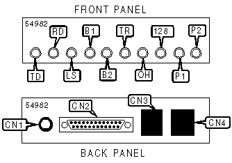
Power, 25-pin DTE serial port, ISDN interface (RJ-45), Auxiliary interface (RJ-11) |
|
ISDN Data Rate |
128Kbps |
|
ISDN Modulation Protocol |
V.110, V.120, X.75, ML-PPP, SoftBond |
|
Error Correction/Compression |
Unidentified |
|
Data Bus |
External |
|
CONNECTIONS | |||
|
Function |
Label |
Function |
Label |
|
Power connector |
CN1 |
Auxiliary interface (RJ-11 connector) |
CN3 |
|
25-pin serial port |
CN2 |
ISDN interface (RJ-45 connector) |
CN4 |
|
DIAGNOSTIC LEDS | |||
|
LED |
Color |
Status |
Condition |
|
TD |
Unidentified |
Blinking |
Data is being transmitted |
|
TD |
Unidentified |
Off |
Data is not being transmitted |
|
RD |
Unidentified |
Blinking |
Data is being received |
|
RD |
Unidentified |
Off |
Data is not being received |
|
LS |
Unidentified |
On |
Link with central office is good |
|
LS |
Unidentified |
Blinking (slow) |
SPIDS have not been verifies with central office |
|
LS |
Unidentified |
Blinking (fast) |
One SPID has been verified with central office |
|
LS |
Unidentified |
Off |
Link with central office is broken |
|
B1 |
Unidentified |
On |
Active data connection on B-channel 1 |
|
B1 |
Unidentified |
Blinking (slow) |
Active analog connection on B-channel 1 |
|
B1 |
Unidentified |
Blinking (fast) |
Connection is being made |
|
B1 |
Unidentified |
Off |
B-channel 1 connection is broken |
|
B2 |
Unidentified |
On |
Active data connection on B-channel 2 |
|
B2 |
Unidentified |
Blinking (slow) |
Active analog connection on B-channel 2 |
|
B2 |
Unidentified |
Blinking (fast) |
Connection is being made |
|
B2 |
Unidentified |
Off |
B-channel 2 connection is broken |
|
TR |
Unidentified |
On |
Data terminal is ready |
|
TR |
Unidentified |
Off |
Data terminal is not ready |
|
OH |
Unidentified |
On |
Device is off-hook |
|
OH |
Unidentified |
Off |
Device is on-hook |
|
128 |
Unidentified |
On |
B-channels have been multiplexed into a single 128Kbps link |
|
128 |
Unidentified |
Off |
B-channels have not been multiplexed into a single 128Kbps link |
|
Note: LED 128 also indicates what protocol is being used in conjunction with P1, and P2 | |||
|
DATA PROTOCOL LEDS | |||
|
Protocol |
128 |
P1 |
P2 |
|
V.110 |
Off |
Off |
Off |
|
V.120 |
Off |
Off |
On |
|
X.75 (1 channel) |
Off |
On |
Off |
|
X.75 (2 channel) |
On |
On |
Off |
|
PPP (1 channel) |
Off |
On |
On |
|
MLPPP (2 channel) |
On |
On |
On |
|
Note: P1 and P2 LEDs blink to indicate active data compression | |||
|
SUPPORTED COMMAND SET |
|
Basic AT Commands |
|
AT, ‘+++’ |
|
A, E, H, Q, V |
|
&S, &Z |
|
S Registers |
|
S0, S1, S2, S3, S4, S5, S25 |
|
Note: See MHI Help File for full command documentation. |
Proprietary AT Command Set
|
COMMUNICATIONS MODE | |
|
Type: |
Configuration |
|
Format: |
AT [cmds] &Mn [cmds] |
|
Description: |
Selects communications mode. |
|
Note: &M1 is not currently supported by TA | |
|
Command |
Mode |
|
&M0 |
Asynchronous mode |
|
&M1 |
Synchronous mode |
|
DATA COMPRESSION | |
|
Type: |
Configuration |
|
Format: |
AT [cmds] &Kn [cmds] |
|
Description: |
Enables/disables data compression |
|
Command |
Function |
|
í &K0 |
Data compression disabled |
|
&K1 |
Data compression enabled |
|
DATA CARRIER DETECT (DCD) | |
|
Type: |
Configuration |
|
Format: |
AT [cmds] &Cn [cmds] |
|
Description: |
Selects whether the DCD option is enabled or disabled |
|
Command |
Function |
|
&C0 |
DCD enabled |
|
í &C1 |
DCD enabled after carrier signal detected |
|
&C2 |
DCD drops after disconnect for a time specified by register S10 |
|
DATA TERMINAL READY (DTR) | ||
|
Type: |
Configuration | |
|
Format: |
AT [cmds] &Dn [cmds] | |
|
Description: |
Selects modem response to DTR | |
|
Command |
Mode | |
|
&D0 |
Ignore transition of DTR status | |
|
í &D1 |
Switch to command mode if DTR is low | |
|
&D2 |
Abort connection if DTR is low, return to command mode and disable auto-answer. If device is off-line, it will neither answer nor dial when DTR is low | |
|
&D3 |
Abort connection and reinitialize on low DTR | |
|
DIAL | |
|
Type: |
Immediate |
|
Format: |
AT [cmds] D<#> [cmds] |
|
Description: |
Dials ISDN telephone number according to any modifiers included in the string |
|
Note: |
Any combination of modifiers can be used to produce the desired dial functions in sequence. |
|
Command |
Function |
|
DS=n |
Dial stored telephone number n |
|
FACTORY DEFAULT PROFILE | |
|
Type: |
Configuration |
|
Format: |
AT [cmds] &F [cmds] |
|
Description: |
Sets values in active profile to values found in the default profile |
|
Command |
Function |
|
&F0 |
Load quick setup profile 0 (modem standard) |
|
&F1 |
Load quick setup profile 1 (V.110) |
|
&F2 |
Load quick setup profile 2 (V.120) |
|
&F3 |
Load quick setup profile 3 (X.75) |
|
&F4 |
Load quick setup profile 4 (MLPPP) |
|
FLOW CONTROL | |
|
Type: |
Configuration |
|
Format: |
AT [cmds] &En [cmds] |
|
Description: |
Enables flow control options |
|
Command |
Function |
|
&E3 |
Flow control disabled |
|
&E4 |
RTS to CTS flow control enabled |
|
&E5 |
XON/XOFF flow control enabled |
|
&E6 |
When pacing is active, XON/XOFF signals are responded to and discarded by TA |
|
&E7 |
When pacing is active, XON/XOFF signals are passed through local modem |
|
&E12 |
XON/XOFF pacing disabled |
|
&E13 |
XON/XOFF pacing enabled |
|
ON-LINE | |
|
Type: |
Immediate |
|
Format: |
AT [cmds] On [cmds] |
|
Description: |
Controls on-line command (data transmission) state options. |
|
Command |
Function |
|
O0 |
On-line command mode with no retraining enabled |
|
LIST ACTIVE PROFILE | |
|
Type: |
Immediate |
|
Format: |
AT [cmds] Ln [cmds] |
|
Description: |
Lists active profile |
|
Command |
Function |
|
L5 |
Lists current operating parameters of TA |
|
L6 |
Lists values currently stored in the S registers |
|
REPORT INFORMATION | |
|
Type: |
Immediate |
|
Format: |
AT [cmds] In [cmds] |
|
Description: |
Displays information requested |
|
Command |
Function |
|
I0 |
Reports product ID |
|
I1 |
Reports firmware version number |
|
I2 |
MTS internal use |
|
RTS/CTS | |
|
Type: |
Configuration |
|
Format: |
AT [cmds] &Rn [cmds] |
|
Description: |
Selects RTS/CTS options |
|
Command |
Function |
|
&R0 |
CTS follows RTS in data mode; RTS is ignored in command mode. |
|
í &R1 |
CTS forced high, RTS is ignored. |
|
&R2 |
CTS is forced high, but drops on disconnect for a time specified by register S10 |
|
SELECT CALL PROGRESS RESULT CODES | |
|
Type: |
Configuration |
|
Format: |
AT [cmds] Xn [cmds] |
|
Description: |
Enables selection of tone detection and associated result code format options |
|
Command |
Function |
|
X0 |
Busy and dial tone detection disabled; result codes 0 - 4 enabled. |
|
X1 |
Busy and dial tone detection disabled; result codes 0 - 5 & 10 - 14, 17 - 19, 28, & 32 enabled. |
|
X2 |
Extended result codes enabled |
|
SOFT RESET | |
|
Type: |
Immediate |
|
Format: |
AT [cmds] Zn [cmds] |
|
Description: |
Restores modem profiles previously saved in non-volatile RAM using the &W command. |
|
STORE ACTIVE PROFILE | |
|
Type: |
Configuration |
|
Format: |
AT [cmds] &Wn [cmds] |
|
Description: |
Writes the values for the active profile into the non-volatile RAM |
|
Command |
Function |
|
&W0 |
Stores all current AT commands and S-register values in NVRAM |
|
í &W1 |
Deletes custom settings on reset or power down. Factory default profile used |
Extended AT Command Set
|
ESCAPE SEQUENCE OPTIONS | |
|
Type: |
Configuration |
|
Format: |
AT [cmds] %En [cmds] |
|
Description: |
Controls escape sequence options |
|
Note: |
%E1 or %E3 may be entered in conjunction with %E5 |
|
Command |
Function |
|
%E0 |
Escape disabled |
|
%E1 |
+++ escape option enabled |
|
%E2 |
<BREAK> escape option enabled |
|
%E3 |
+++ and <BREAK> escape options enabled |
|
%E4 |
OK response to +++ disabled |
|
%E5 |
OK response to +++ enabled |
|
SENDING METHOD | |
|
Type: |
Configuration |
|
Format: |
AT [cmds] %A97=n [cmds] |
|
Description: |
Selects whether a "sending complete indication" signal is sent or overlap sending is implemented |
|
Command |
Function |
|
%A97=0 |
En bloc sending during cal SETUP enabled |
|
%A97=1 |
Overlap sending during call SETUP enabled |
|
SERIAL PORT MODE | ||
|
Type: |
Configuration | |
|
Format: |
AT [cmds] %Sn [cmds] | |
|
Description: |
Selects serial port speed | |
|
Command |
Function | |
|
%S0 |
Automatic speed selection enabled | |
|
%S1 |
460.8Kbs | |
Special Commands
|
CONFIGURATION | |
|
Type: |
Configuration |
|
Format |
AT [cmds] @CONFIG [cmds] |
|
Description: |
Starts the internal configuration utility. Command must be entered in terminal mode |
|
DATA DIRECTORY NUMBER | |
|
Type: |
Configuration |
|
Format: |
AT [cmds] !N1=n [cmds] |
|
Range: |
0 – 24 |
|
Unit: |
0 - 9, *, # |
|
Description: |
Sets the directory number (DN) for the data channel |
|
DATA SPID | |
|
Type: |
Configuration |
|
Format: |
AT [cmds] !C6=n [cmds] |
|
Range: |
0 – 20 |
|
Unit: |
ASCII |
|
Description: |
Specifies the data service profile identifier assigned by the ISDN provider |
|
DATA TEI | |
|
Type: |
Configuration |
|
Format: |
AT [cmds] !D3=n [cmds] |
|
Range: |
0 - 63, 240, 241 |
|
Unit: |
ASCII |
|
Description: |
Sets the terminal endpoint identifier for the data channel. 240 (default) sets to automatic. 241 disables |
|
DISPLAY NETWORK CONFIGURATION | |
|
Type: |
Immediate |
|
Format: |
AT [cmds] !L [cmds] |
|
Description: |
Displays the current DN, SPID, TEI, data protocol; and switch type |
|
EMBEDDED PROTOCOL ANALYZER | |
|
Type: |
Configuration |
|
Format: |
AT [cmds] >Dn [cmds] |
|
Description: |
Analyzes various protocols |
|
Command |
Function |
|
>D0 |
Display B-channel traffic, decoded as V.120 |
|
>D1 |
Display D-channel traffic, decoding layers 2 & 3 |
|
>D2 |
Display D-channel traffic, decoding layers 2 |
|
>D3 |
Display D-channel traffic, decoding layers 3 |
|
>D4 |
Display B-channel traffic, decoded as X.75 |
|
>D98 |
Embedded protocol analyzer disabled |
|
>D99 |
Embedded protocol analyzer enabled |
|
ISDN D-CHANNEL PROTOCOL | |
|
Type: |
Configuration |
|
Format: |
AT [cmds] !C0=n [cmds] |
|
Description: |
Selects network switch type |
|
Command |
Function |
|
!C0=0 |
AT&T 5ESS |
|
!C0=1 |
Northern Telecom DMS-100 |
|
í !C0=2 |
Euro-ISDN NET3 |
|
!C0=3 |
1TR6 |
|
!C0=4 |
INS64 |
|
!C0=5 |
US NI-1 |
|
!C0=6 |
VN4 |
|
PERSISTANT DTR DIALING | |
|
Type: |
Configuration |
|
Format: |
AT [cmds] $Dn [cmds] |
|
Description: |
Enables/disables persistent DTR dialing |
|
Command |
Function |
|
í $D0 |
PDD disabled |
|
$D1 |
PDD enabled |
|
POWER UP DATA BITS | |
|
Type: |
Configuration |
|
Format |
AT [cmds] @P4=n [cmds] |
|
Description: |
Sets the data bits at power up |
|
Command |
Function |
|
@P4=7 |
7 bits |
|
@P4=8 |
8 bits |
|
POWER UP PARITY | |
|
Type: |
Configuration |
|
Format |
AT [cmds] @P3=n [cmds] |
|
Description: |
Sets the parity at power up |
|
Command |
Function |
|
@P3=0 |
Odd parity enabled |
|
@P3=1 |
Even parity enabled |
|
@P3=2 |
Mark parity enabled |
|
@P3=3 |
Space parity enabled |
|
@P3=4 |
Parity disabled |
|
POWER UP SPEED | |
|
Type: |
Configuration |
|
Format |
AT [cmds] $SBn [cmds] |
|
Description: |
Sets the serial speed negotiated when the TA powers up. If the speed is set to 460.8Kbps than the %S1 mode is initialized. %S1 mode is used for any other rate. |
|
Command |
Function |
|
$SB3 |
300bps |
|
$SB12 |
1200bps |
|
$SB24 |
2400bps |
|
$SB48 |
4800bps |
|
$SB96 |
9600bps |
|
$SB192 |
19.2Kbps |
|
$SB384 |
38.4Kbps |
|
$SB576 |
57.6Kbps |
|
$SB1152 |
115.2Kbps |
|
$SB2304 |
230.4Kbps |
|
$SB3608 |
460.8Kbps |
|
POWER UP STOP BITS | |
|
Type: |
Configuration |
|
Format |
AT [cmds] @P6=n [cmds] |
|
Description: |
Sets the data bits at power up |
|
Command |
Function |
|
@P6=1 |
1 stop bit |
|
@P6=2 |
2 stop bits |
|
RATE ADAPTION PROTOCOL | |
|
Type: |
Configuration |
|
Format: |
AT [cmds] !Z=n [cmds] |
|
Description: |
Select rate adaption protocol used to communicate with another TA |
|
Command |
Function |
|
!Z=5 |
V.120 |
|
!Z=6 |
V.110 |
|
!Z=9 |
ML-PPP |
|
!Z=12 |
X.75 |
|
RECEIVE GAIN | |
|
Type: |
Configuration |
|
Format: |
AT [cmds] !RXGn [cmds] |
|
Range: |
0 - 10 |
|
Unit: |
ASCII |
|
Description: |
Controls the speaker level of an analog telephone device connected to the AUX port |
|
TRANSMIT GAIN | |
|
Type: |
Configuration |
|
Format: |
AT [cmds] !TXGn [cmds] |
|
Range: |
0 - 4 |
|
Unit: |
ASCII |
|
Description: |
Controls microphone amplification of an analog telephone device connected to the AUX port |
|
Note: Do not adjust the gain unless it is absolutely necessary. It is very high at non-zero levels. | |
|
VOICE DIRECTORY NUMBER | |
|
Type: |
Configuration |
|
Format: |
AT [cmds] *!N1=n [cmds] |
|
Range: |
0 - 24 |
|
Unit: |
0 - 9, *, # |
|
Description: |
Sets the directory number (DN) for the voice channel |
|
VOICE SPID | |
|
Type: |
Configuration |
|
Format: |
AT [cmds] *!C6=n [cmds] |
|
Range: |
0 - 20 |
|
Unit: |
ASCII |
|
Description: |
Specifies the voice service profile identifier assigned by the ISDN provider |
|
VOICE TEI | |
|
Type: |
Configuration |
|
Format: |
AT [cmds] *!D3=n [cmds] |
|
Range: |
0 - 63, 240, 241 |
|
Unit: |
ASCII |
|
Description: |
Sets the terminal endpoint identifier for the voice channel. 240 (default) sets to automatic. 241 disables |
|
XOFF SENDING | |
|
Type: |
Configuration |
|
Format: |
AT [cmds] #Xn [cmds] |
|
Description: |
Determines whether single or multiple XOFF characters are sent |
|
Command |
Function |
|
í #X0 |
One XOFF character is sent until the buffer reaches the XON level |
|
#X1 |
Multiple XOFF characters are sent for every character received after buffer reaches full level. |
S(Status) Registers
|
AUTO-PROTOCOL DETECTION | |
|
Type: |
Register |
|
Format |
AT [cmds] S52=n [cmds] |
|
Description: |
Enables/disables mechanism for identifying type of protocol |
|
Command |
Function |
|
S52=0 |
Auto-protocol detection disabled |
|
í S52=1 |
Auto-protocol detection enabled |
|
CALLER LINE ID | |
|
Type: |
Register |
|
Format |
AT [cmds] S50=n [cmds] |
|
Description: |
Enables/disables mechanism for identifying the two endpoints of a connection |
|
Command |
Function |
|
S50=0 |
CLI feature disabled |
|
í S50=1 |
CLI feature enabled |
|
CARRIER LOSS RESPONSE TIME | |
|
Type: |
Register |
|
Format |
AT [cmds] S10=n [cmds] |
|
Range: |
0-255 |
|
Unit: |
.05 second |
|
Description: |
Maximum time allowed by the modem after losing the carrier signal and prior to initiating hang-up process. |
|
ESCAPE SEQUENCE | |
|
Type: |
Register |
|
Format: |
AT [cmds] S32=n [cmds] |
|
Range: |
0-255 |
|
Unit: |
.1sec |
|
Description: |
Maximum time allowed by the modem in an escape sequence |
|
MAXIMUM FRAME SIZE | |
|
Type: |
Register |
|
Format: |
AT [cmds] S53=n [cmds] |
|
Range: |
0-2048 |
|
Unit: |
ASCII |
|
Description: |
Sets the maximum frame size of data frames in X.75 mode |
|
NO CARRIER TIME-OUT | |
|
Type: |
Register |
|
Format |
AT [cmds] S7=n [cmds] |
|
Range: |
0-255 |
|
Unit: |
1 second |
|
Description: |
Maximum wait time the modem uses after dialing to detect a carrier signal from the remote modem for both originating and answering calls. Default=45 |